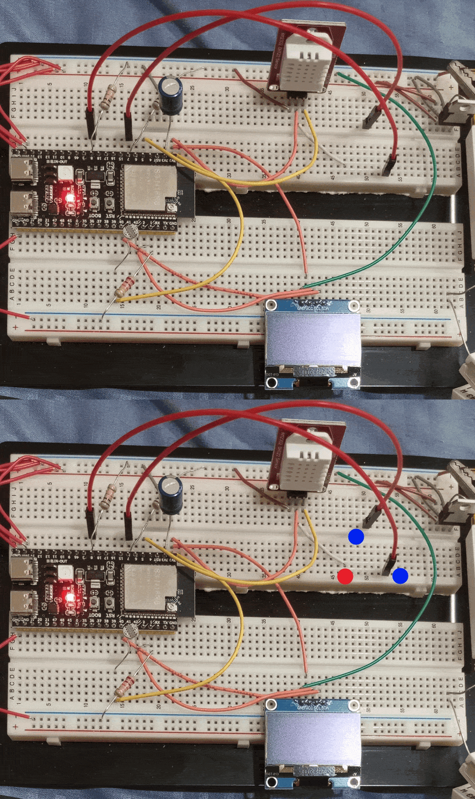
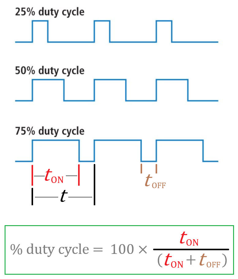
วันนี้จะขอเสนอการใช้งาน ESP32 ในงาน PWM …. PWM ย่อมาจาก Pulse Width Modulation มันคือการกำเนิดลูกคลื่นสี่เหลี่ยมในความถี่ต่าง ๆ และสามารถเปลี่ยนแปลงค่าของ % duty cycle ได้ การกำเนิด PWM แบบนี้มีประโยชน์หลายงานแล้วแต่งานที่เราต้องการจะทำครับ โดยหลักเลยก็คือการควบคุมความเร็วของมอเตอร์แบบ BLDC และยังสามารถใช้ในการควบคุมความสว่างของหลอดไฟขนาดเล็กอย่างเช่น LED ได้ด้วยการป้อน PWM เข้าไปใน LED ด้วย duty cycle ที่เปลี่ยนแปลงระหว่างช่วง 10 – 90% ซึ่งจะทำให้ LED สว่างน้อยถึงมาก
ก่อนอื่นมาดูลักษณะของรูปคลื่น PWM ก่อนว่าลักษณะของ duty cycle ว่ามันจะเป็นอย่างไร จากภาพนี้จะเห็นว่ารูปคลื่นสี่เหลี่ยมจะมีความกว้างช่วง ON และ OFF ใน 1 ช่วงคลื่น ถ้าช่วง ON มีค่าน้อยก็หมายความว่า % ของ duty cycle มีค่าต่ำ และหากช่วง ON กว้างและช่วง OFF แคบนิดเดียวก็คือรูปคลื่นนั้นมี % ของ duty cycle สูงครับ
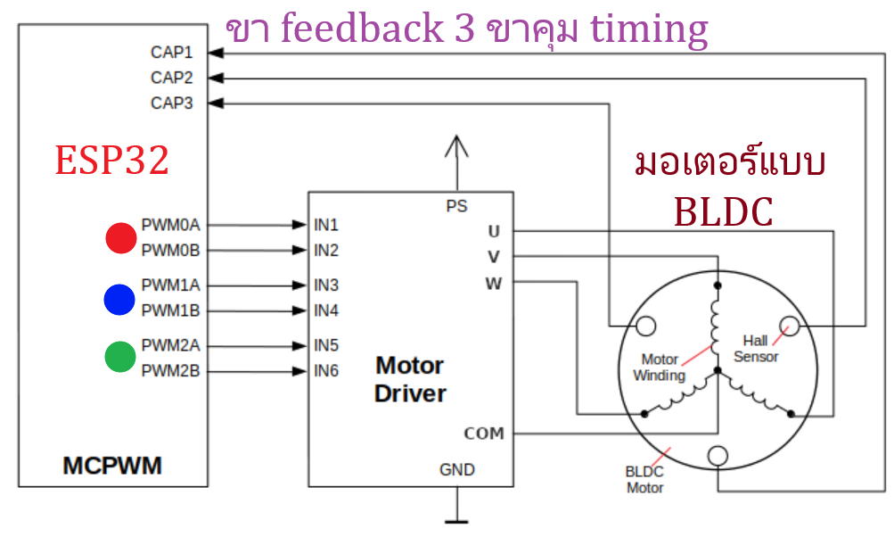
ใน ESP32 จะมี hardware ที่ทำหน้าที่กำเนิด PWM โดยเฉพาะ นั่นก็หมายความว่าในการกำเนิด PWM จะไม่กินกำลัง CPU ของ ESP32 เลยเพราะมันเป็น dedicated hardware ซึ่งจะแบ่งเป็น 2 ส่วนก็คือ
🛑 LEDC (LED Controller) เป็นส่วนของ hardware ที่ออกแบบสำหรับใช้งานแบบ basic สามารถนำไปคุมความสว่างของ LED ก็ได้ หรือกำเนิดคลื่นสี่เหลี่ยมเพื่อใช้งานอเนกประสงค์ใด ๆ ก็ได้โดยสามารถปรับ duty cycle ได้อย่างอิสระ อย่างในโปรเจคที่ผมจะสาธิตด้านล่างนี้สามารถกำเนิดได้กว้างมากถึง 5 Hz – 1 MHz และปรับ duty cycle ได้กว้างในช่วง 5 – 95% โดยทำงานผ่าน web dashboard
🛑 MCPWM (Motor Control Pulse Width Modulator) ส่วนนี้จะทำงานค่อนข้างซับซ้อนเนื่องจากออกแบบให้ควบคุมมอเตอร์แบบ 3 เฟส ดังนั้นจึงให้ output ได้ถึง 3 ชุดและมีขารองรับการป้อนกลับจากตัวมอเตอร์เพื่อสร้าง timing ที่แม่นยำ
ต่อไปจะว่าด้วยข้อจำกัดของในการกำเนิด PWM …. เนื่องจาก ESP32 ทำงานด้วยสัญญาณนาฬิกา clock ความถี่ 80 MHz จาก APB (Advanced Peripheral Bus) ดังนั้นจึงมีข้อจำกัดอยู่เล็กน้อยในการกำเนิดที่ความถี่สูงระดับ 1 MHz หรือประมาณนี้ สิ่งที่ว่านี้ก็คือ Resolution ของ duty cycle
จาก clock 80 MHz ของ ESP32 เมื่อ LEDC ทำงานภายในตัวจะมี counter ภายใน หากเรากำหนดให้สร้างความถี่ 1 MHz ตัว counter ของ LEDC ก็จะสามารถนับได้เท่ากับ 80 ticks ซึ่งจำนวน 80 ticks ที่นับได้นี้ค่าของ resolution ก็จะมีค่าประมาณ 6 bit ตามสมการ log นี้
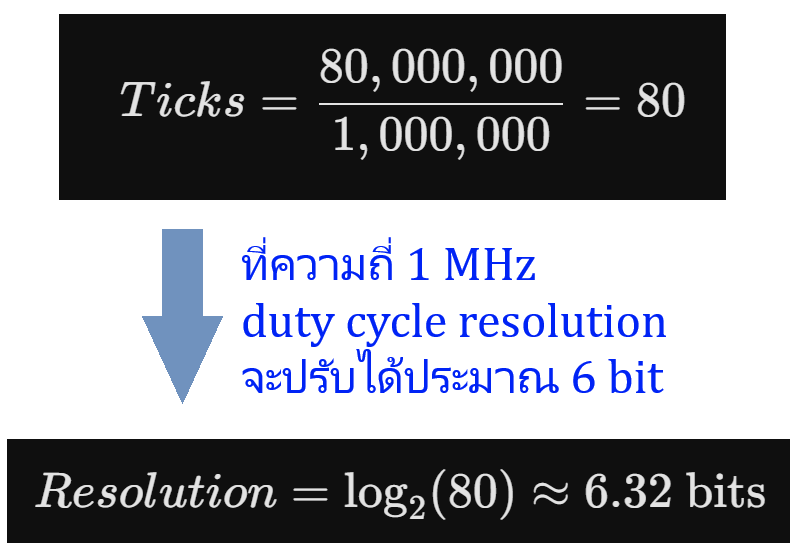
และหากเรากำเนิดที่ความถี่ต่ำกว่านี้อย่างเช่น 40 KHz ค่า resolution ก็จะประมาณ 10 bit
ค่า resolution ที่เป็นจำนวน bit นี้มันหมายความถึง step ของ duty cycle ที่สามารถทำได้ อย่างที่ความถี่ 1 MHz = resolution เท่ากับ 6 bit ดังนั้น steps ของค่า duty cycle ที่จะเปลี่ยนแปลงได้ก็จะ = 26 = 64 steps ก็คือ duty cycle 0 – 100% จะเริ่มต้นจาก (100/64) = 1.5625% → 3.125 → 4.6875 6.25 7.8125 9.375 …. 50 51.5625 ไปจนถึง 98.4375 %
และหากที่ความถี่ต่ำกว่านี้เช่น 40 KHz ค่า resolution ก็จะประมาณ 10 bit และหาความถี่ต่ำลงไปอีกก็จะสามารถปรับ step ของ duty cycle ได้อย่างละเอียดมากกว่านี้อีกแต่ก็สูงสุดก็คือ 16 bit ครับ 0.09765625 → 0.1953125 → 0.29296875 → 0.390625 …. ซึ่งละเอียดมาก
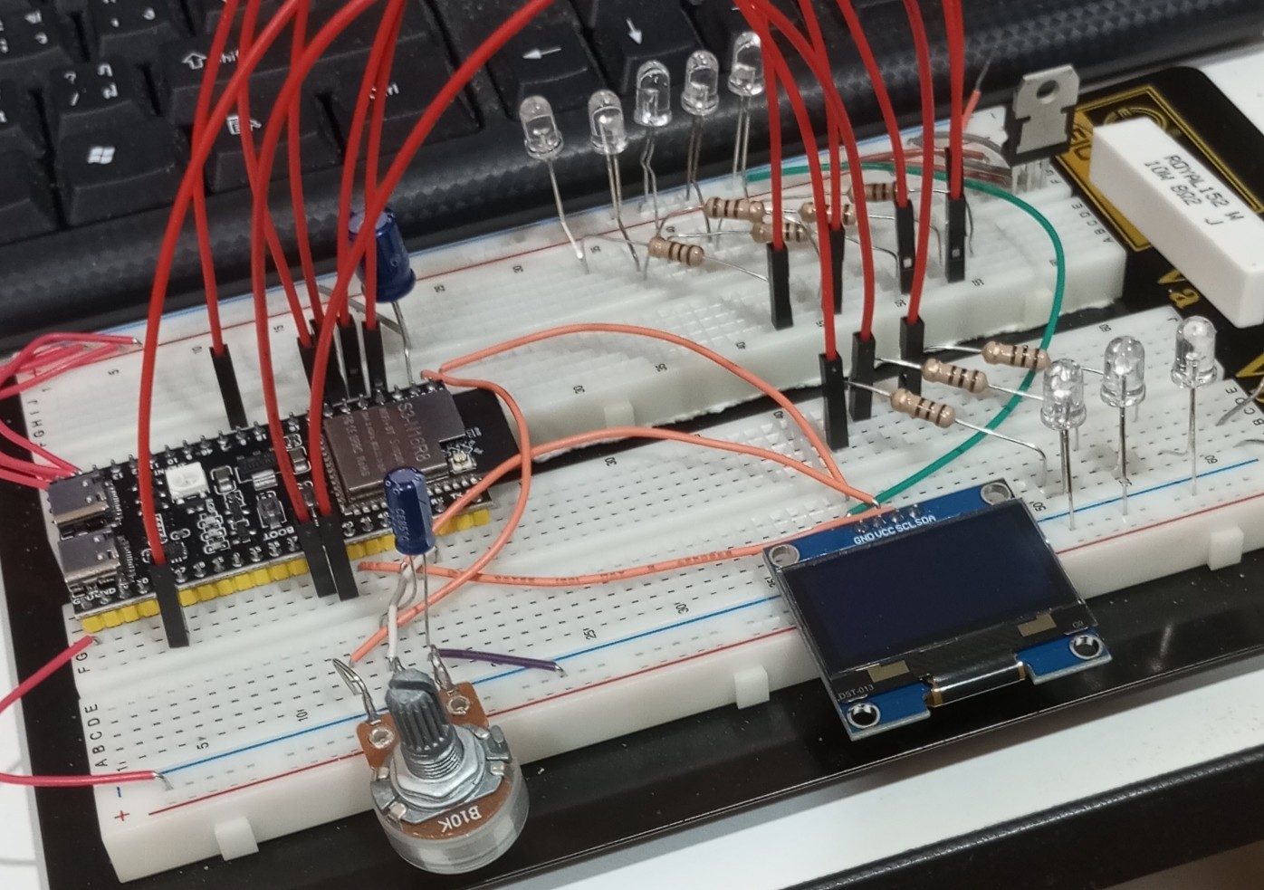
ในคลิปที่ท่านเห็นด้านล่างนี้คือไฟวิ่งที่ออกแบบให้การวิ่งของ LED 5 ดวงนี้เป็นไปแบบ smooth fade นั่นก็คือใช้ PWM มาช่วยครับ โดยเปลี่ยนจากการกระพริบธรรมดาคือเปลี่ยนจาก logic 1 และ 0 ของ GPIO ให้เป็นกำเนิด PWM ออกมาจาก GPIO ทั้ง 5 ขา โดยในช่วงการเปลี่ยนการวิ่งระหว่าง LED แต่ละดวงก็ป้อน PWM ที่มี duty cycle เปลี่ยนแปลงระหว่าง 10 – 90% ทำให้ลักษณะของไฟวิ่งจะดูนุ่มนวลอย่างที่เห็นครับ
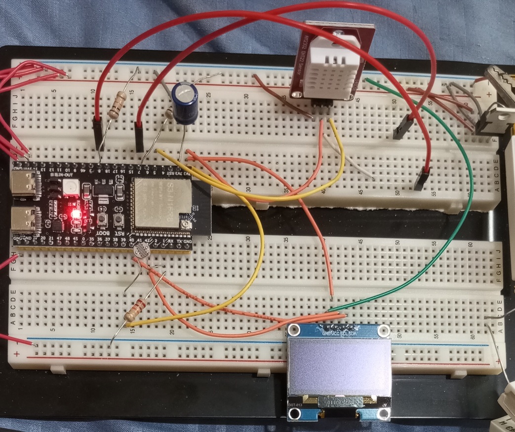
อุปกรณ์ที่ใช้มีเพียงเท่านี้
Code ทั้งหมดของไฟวิ่ง PWM
// Define Pins for both groups
const int pinsGroupA[] = {21, 38, 39}; // 3 LEDs (Simple ON/OFF running)
const int numGroupA = 3;

const int pinsGroupB[] = {4, 5, 6, 7, 8}; // 5 LEDs (Smooth PWM Fading)
const int numGroupB = 5;

const int potPin = 1;

// PWM Settings for ESP32-S3 (Core 3.x)
const int pwmFreq = 5000;       // 5 kHz PWM frequency
const int pwmResolution = 8;    // 8-bit resolution (0 - 255 brightness)
const int maxBrightness = 255;

// State Machine States
enum RunState {
  MODE_THREE_LEDS,
  MODE_FIVE_LEDS
};
RunState currentState = MODE_THREE_LEDS;

// Sequencer Variables
int currentLedIdx = 0;
int previousLedIdx = -1;
int cycleCount = 0;

unsigned long lastRunMillis = 0;
unsigned long lastFadeMillis = 0;
const int fadeInterval = 5; // Update fade every 5ms
float fadeProgress = 0.0;

void setup() {
  // Initialize Group A (3 LEDs) as standard digital outputs
  for (int i = 0; i < numGroupA; i++) {
    pinMode(pinsGroupA[i], OUTPUT);
    digitalWrite(pinsGroupA[i], LOW);
  }

  // Initialize Group B (5 LEDs) using the Core 3.x PWM API
  for (int i = 0; i < numGroupB; i++) {
    ledcAttach(pinsGroupB[i], pwmFreq, pwmResolution);
    ledcWrite(pinsGroupB[i], 0);
  }

  analogReadResolution(12); // 12-bit ADC (0-4095)
}

void loop() {
  unsigned long currentMillis = millis();

  // --- STATE 1: 3 LEDs Running at Fixed 3 Hz ---
  if (currentState == MODE_THREE_LEDS) {
    unsigned long runIntervalA = 1000 / 3; // Fixed 3 Hz frequency -> ~333ms per step

    if (currentMillis - lastRunMillis >= runIntervalA) {
      lastRunMillis = currentMillis;

      // Turn off previous LED
      if (previousLedIdx != -1) {
        digitalWrite(pinsGroupA[previousLedIdx], LOW);
      }

      // Turn on current LED
      digitalWrite(pinsGroupA[currentLedIdx], HIGH);

      // Track sequencing indices
      previousLedIdx = currentLedIdx;
      currentLedIdx++;

      // Check if one full cycle of 3 LEDs is complete
      if (currentLedIdx >= numGroupA) {
        currentLedIdx = 0;
        cycleCount++;

        // If 3 complete cycles are reached, reset and switch state
        if (cycleCount >= 3) {
          // Clean up Group A states
          digitalWrite(pinsGroupA[previousLedIdx], LOW);

          // Switch to Group B
          currentState = MODE_FIVE_LEDS;
          cycleCount = 0;
          currentLedIdx = 0;
          previousLedIdx = numGroupB - 1; // Prepare fading index for Group B
          fadeProgress = 0.0;
        }
      }
    }
  }

  // --- STATE 2: 5 LEDs Running with Smooth Fade + Variable POT Speed ---
  else if (currentState == MODE_FIVE_LEDS) {
    // Read POT to calculate variable frequency (1Hz to 5Hz)
    int potValue = analogRead(potPin);
    float frequency = map(potValue, 0, 4095, 100, 500) / 100.0;
    unsigned long runIntervalB = 1000 / frequency; // Dynamic step time based on frequency

    // A. Handle Smooth Fading Calculations (Every 5ms)
    if (currentMillis - lastFadeMillis >= fadeInterval) {
      lastFadeMillis = currentMillis;

      unsigned long timePassed = currentMillis - lastRunMillis;
      fadeProgress = (float)timePassed / (float)runIntervalB;
      if (fadeProgress > 1.0) fadeProgress = 1.0;

      int fadeInDuty = fadeProgress * maxBrightness;
      int fadeOutDuty = (1.0 - fadeProgress) * maxBrightness;

      // Apply smooth PWM fading to current and previous LEDs
      ledcWrite(pinsGroupB[currentLedIdx], fadeInDuty);
      ledcWrite(pinsGroupB[previousLedIdx], fadeOutDuty);
    }

    // B. Handle stepping to the next LED in Group B
    if (currentMillis - lastRunMillis >= runIntervalB) {
      lastRunMillis = currentMillis;

      // Ensure clean final values for step transition
      ledcWrite(pinsGroupB[previousLedIdx], 0);
      ledcWrite(pinsGroupB[currentLedIdx], maxBrightness);

      previousLedIdx = currentLedIdx;
      currentLedIdx++;

      // Check if one full cycle of 5 LEDs is complete
      if (currentLedIdx >= numGroupB) {
        currentLedIdx = 0;
        cycleCount++;

        // If 3 complete cycles are reached, reset and switch state back to Group A
        if (cycleCount >= 3) {
          // Clean up Group B states
          ledcWrite(pinsGroupB[previousLedIdx], 0);

          // Switch to Group A
          currentState = MODE_THREE_LEDS;
          cycleCount = 0;
          currentLedIdx = 0;
          previousLedIdx = -1; // Reset to safe initial value for Group A
        }
      }

      fadeProgress = 0.0; // Reset fade progress for the new step
    }
  }
}
ต่อไปคือ project จริงที่ใช้ประโยชน์สูงสุดจากของ PWM โดยออกแบบให้กำเนิดความถี่ในช่วงกว้างมากระหว่าง 5 Hz – 1 MHz และสามารถปรับ duty cycle ได้ช่วงกว้างระหว่าง 5 – 95% ครับและเพื่อความสะดวกก็ออกแบบให้รับค่าความถี่และ duty cycle จาก web dashboard ได้เลยดูรายละเอียดในคลิปครับ
Code ทั้งหมดของ PWM generator + web dashboard
#include <WiFi.h>
#include <WebServer.h>

// --- WiFi Credentials ---
const char* ssid = " SSID ของ Wi-Fi ท่าน";
const char* password = " password ของ Wi-Fi ท่าน ";

// --- Hardware Settings ---
const uint8_t PWM_PIN = 11;
uint32_t currentFreq = 1000; // Default 1 kHz
uint8_t currentDuty = 50;    // Default 50%

WebServer server(80);

// --- HTML/CSS/JS Dashboard ---
// Stored in program memory (PROGMEM) to save RAM
const char index_html[] PROGMEM = R"rawliteral(
<!DOCTYPE html>
<html>
<head>
  <meta name="viewport" content="width=device-width, initial-scale=1">
  <title>ESP32-S3 PWM Controller</title>
  <style>
    body { font-family: Arial, sans-serif; text-align: center; background-color: #f4f4f9; padding: 20px; }
    .card { background: white; padding: 30px; border-radius: 10px; box-shadow: 0 4px 8px rgba(0,0,0,0.1); display: inline-block; max-width: 100%; overflow-x: hidden; }
    h2 { color: #333; }
    .slider-container { margin: 30px 0; }
    input[type=range] { width: 100%; max-width: 400px; }

    /* PC Specific styling: 1200px wide sliders */
    @media (min-width: 1024px) {
      input[type=range] { width: 1200px; max-width: 1200px; }
      .card { max-width: 1300px; }
    }
    slider
    .value-label { font-size: 1.2em; font-weight: bold; color: #0066cc; }
    input[type=number] { padding: 10px; font-size: 1em; width: 150px; text-align: center; border: 1px solid #ccc; border-radius: 5px; }
    button { padding: 10px 20px; font-size: 1em; background-color: #0066cc; color: white; border: none; border-radius: 5px; cursor: pointer; }
    button:hover { background-color: #004c99; }
  </style>
</head>
<body>
  <div class="card">
    <h2>ESP32-S3 PWM Dashboard</h2>

    <div class="slider-container">
      <h3>Frequency (Hz)</h3>
      <input type="range" id="freqSlider" min="1" max="1000000" value="1000" oninput="updateFreqFromSlider()">
      <br><br>
      <input type="number" id="freqInput" min="1" max="1000000" value="1000" oninput="updateFreqFromInput()">
      <button onclick="executeSend()">Send</button>
    </div>

    <hr>

    <div class="slider-container">
      <h3>Duty Cycle (%)</h3>
      <input type="range" id="dutySlider" min="5" max="95" step="5" value="50" oninput="onDutySlide()">
      <p class="value-label"><span id="dutyLabel">50</span>%</p>
    </div>
  </div>

  <script>
    let canSend = true;

    // Sync input box when slider moves and throttle network request
    function updateFreqFromSlider() {
      document.getElementById("freqInput").value = document.getElementById("freqSlider").value;
      throttleSend();
    }

    // Sync slider when input box changes (User types value)
    function updateFreqFromInput() {
      let val = document.getElementById("freqInput").value;
      // Clamp values between 1 and 1,000,000
      if(val < 1) val = 1;
      if(val > 1000000) val = 1000000;
      document.getElementById("freqSlider").value = val;
    }

    // Update duty label and throttle network request
    function onDutySlide() {
      document.getElementById("dutyLabel").innerText = document.getElementById("dutySlider").value;
      throttleSend();
    }

    // Ensures we only send HTTP GET every 1 second maximum while sliding
    function throttleSend() {
      if(canSend) {
        executeSend();
        canSend = false;
        setTimeout(() => { canSend = true; }, 1000); // 1000ms = 1 second
      }
    }

    // The actual HTTP GET request
    function executeSend() {
      let f = document.getElementById("freqInput").value;
      let d = document.getElementById("dutySlider").value;

      fetch(`/update?freq=${f}&duty=${d}`)
        .then(response => { console.log("PWM Updated"); })
        .catch(error => { console.error("Error updating PWM", error); });
    }
  </script>
</body>
</html>
)rawliteral";

// --- Function to update hardware PWM based on ESP32 Core v3.x API ---
// --- Function to update hardware PWM based on ESP32 Core v3.x API ---
void setPWM(uint32_t freq, uint8_t dutyPercent) {
  // 1. Calculate the maximum bit resolution for this frequency
  uint8_t resolution = log2(80000000 / freq);

  // Clamp resolution to a maximum of 14 bits for stability, and minimum of 1 bit
  if (resolution > 14) resolution = 14;
  if (resolution < 1) resolution = 1;

  // 2. THE FIX: Update frequency dynamically
  // ledcChangeFrequency returns 0 if the pin hasn't been attached yet.
  // So if it fails (like during the first run in setup()), we use ledcAttach instead.
  if (ledcChangeFrequency(PWM_PIN, freq, resolution) == 0) {
    ledcAttach(PWM_PIN, freq, resolution);
  }

  // 3. Convert the percentage (5-95%) into the raw hardware value based on resolution
  uint32_t max_duty_value = (1 << resolution) - 1;
  uint32_t raw_duty = (dutyPercent * max_duty_value) / 100;

  // 4. Write the value to the hardware
  ledcWrite(PWM_PIN, raw_duty);

  Serial.printf("Set PWM -> Freq: %d Hz | Duty: %d%% | Res: %d-bit | Raw Duty: %d/%d\n",
                freq, dutyPercent, resolution, raw_duty, max_duty_value);
}

void setup() {
  Serial.begin(115200);
  ledcSetClockSource(LEDC_USE_APB_CLK);
  // Initialize PWM with default values
  setPWM(currentFreq, currentDuty);

  // Connect to Wi-Fi
  Serial.print("Connecting to WiFi: ");
  Serial.println(ssid);
  WiFi.mode(WIFI_STA);
  WiFi.begin(ssid, password);

  while (WiFi.status() != WL_CONNECTED) {
    delay(500);
    Serial.print(".");
  }
  Serial.println("\nWiFi Connected!");
  Serial.print("IP Address: ");
  Serial.println(WiFi.localIP());

  // --- Web Server Routes ---

  // 1. Serve the Dashboard
  server.on("/", []() {
    server.send(200, "text/html", index_html);
  });

  // 2. Handle the HTTP GET request from JS (e.g. /update?freq=500000&duty=45)
  server.on("/update", []() {
    if (server.hasArg("freq") && server.hasArg("duty")) {
      currentFreq = server.arg("freq").toInt();
      currentDuty = server.arg("duty").toInt();

      // Safety clamps
      if(currentFreq < 1) currentFreq = 1;
      if(currentFreq > 1000000) currentFreq = 1000000;
      if(currentDuty < 5) currentDuty = 5;
      if(currentDuty > 95) currentDuty = 95;

      setPWM(currentFreq, currentDuty);
      server.send(200, "text/plain", "OK");
    } else {
      server.send(400, "text/plain", "Missing parameters");
    }
  });

  server.begin();
  Serial.println("HTTP server started");
}

void loop() {
  // Listen for incoming web requests
  server.handleClient();
}