ตั้งแต่ยุคของ Arduino ก็มีพวก sensor ชนิดต่าง ๆ เกือบ 100 ชนิดก็ว่าได้ มีทั้ง sensor แบบ analog , digital ซึ่ง sensor เหล่านั้นก็นำมาใช้กับ ESP32 ได้อย่างสมบูรณ์ สิ่งเดียวที่ต้องดูก็คือ sensor เหล่านั้นใช้ไฟเลี้ยงเท่าใด 5 โวลต์หรือ 3.3 โวลต์ หากเป็น sensor ในยุคของ Arduino ก็จะเป็นไฟเลี้ยง 5 โวลต์ เมื่อเชื่อมต่อกับ ESP32 (ซึ่งรับ input เข้า GPIO 3.3V) ก็จะต้องมีอุปกรณ์ลดแรงดันลงจากเกือบ 5V เป็น 3.3V (ใช้ voltage divider ง่ายสุด)
ภาพตัวอย่าง sensors ที่ใช้กับ ESP32 , Arduino
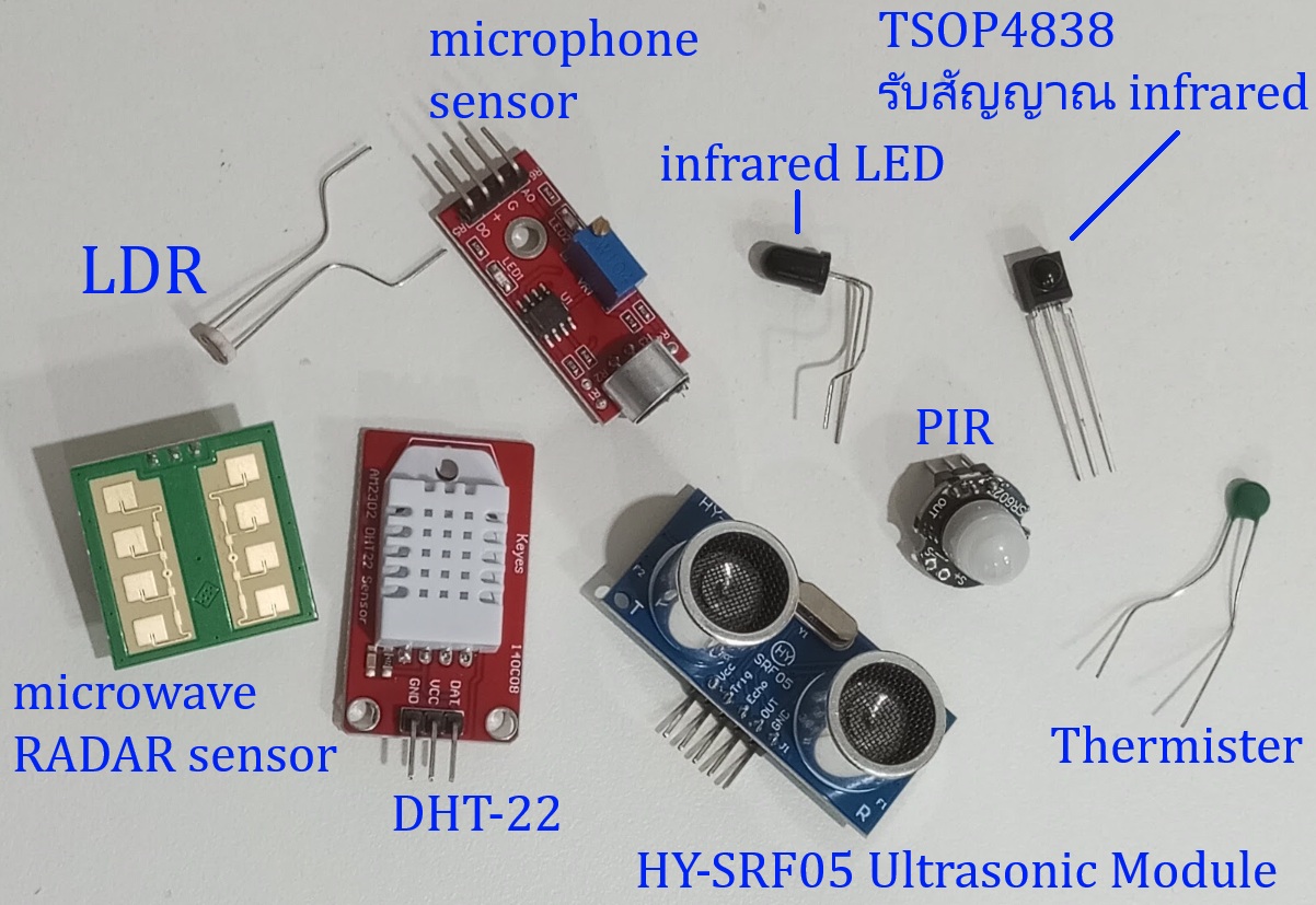
sensor ทั้งหลายเหล่านี้ถูกผลิตออกมาครอบคลุมการใช้งาน IoT ทั้งหมด ที่ใช้กันมากก็เช่น sensor อุณหภูมิ ความชื้น ความสว่าง ระดับเสียง วัดระยะทาง นอกจากนี้ยังมี sensor พื้นฐานที่ใช้ในอิเล็กทรอนิกส์ยุคเก่ามาประยุกต์เชื่อมต่อกับ ESP32 ก็ได้อย่างเช่น LDR , Thermistor , ตัวรับสัญญาณ infrared , IR LED
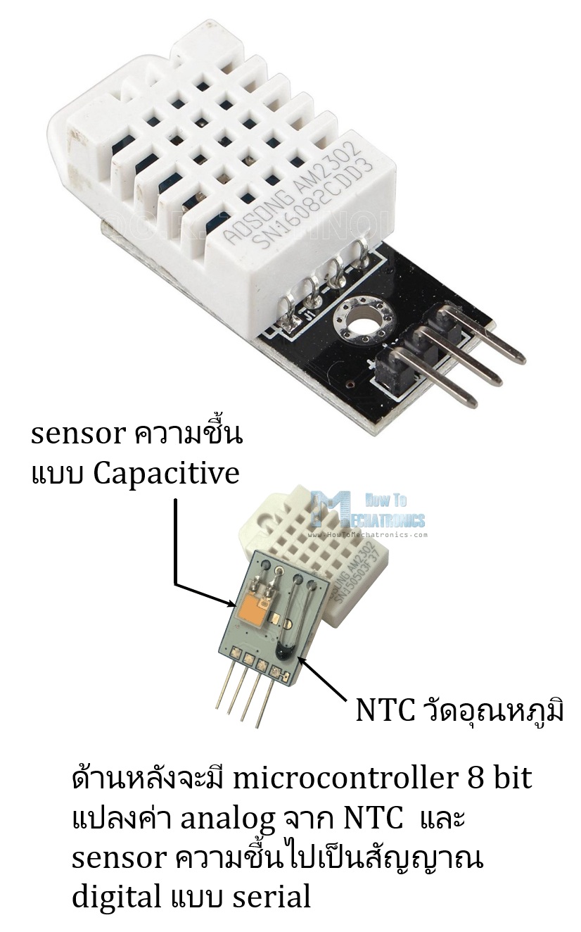
🛑 ตัวแรกก็คือ DHT22 มันเป็น sensor อุณหภูมิกับความชื้นแบบ digital ก็คือมีขา output เพียงขาเดียวเท่านั้นและต่อกับ GPIO ของ ESP32 โดยตรงได้เลยครับเพราะใช้ไฟเลี้ยง 3.3V ข้างใน sensor ตัวนี้จะมี sensor รับความชื้นและ Thermister เพื่อรับอุณหภูมิและมีไมโครคอนโทรลเลอร์ 8 bit ขนาดจิ๋วด้านในเพื่อแปลงสัญญาณ analog จาก sensor ความชื้นและ thermister แปลงไปเป็นสัญญาณ serial และเนื่องจาก DHT22 เป็นแบบ digital output ดังนั้นจึงต้องทำงานกับ library ของมันเอง
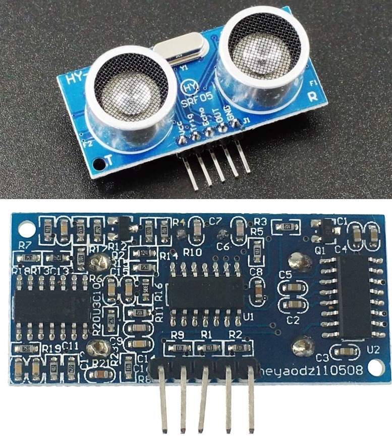
🛑 ตัวต่อไปคือ HY-SRF05 Ultrasonic Module เป็น sensor ที่ใช้คลื่นเสียงความถี่สูงระดับ ultrasonic 40 KHz โดยส่งคลื่นออกไปและคำนวณเวลาที่คลื่นสะท้อนกลับมา สามารถวัดระยะวัตถุได้แม่นยำตั้งแต่ 2 ซม. – 4 เมตร ตัวนี้เป็น sensor ที่สมบูรณ์ในตัวเอง ก็คือมี IC ทำหน้าที่กำเนิด ultrasonic และเป็นภาครับ echo ของคลื่น ultrasonic กลับมาแปลงมาเป็นค่า timing ได้เลย
Timing diagram ของ HY-SRF05 Ultrasonic Module ตามภาพนี้ครับ
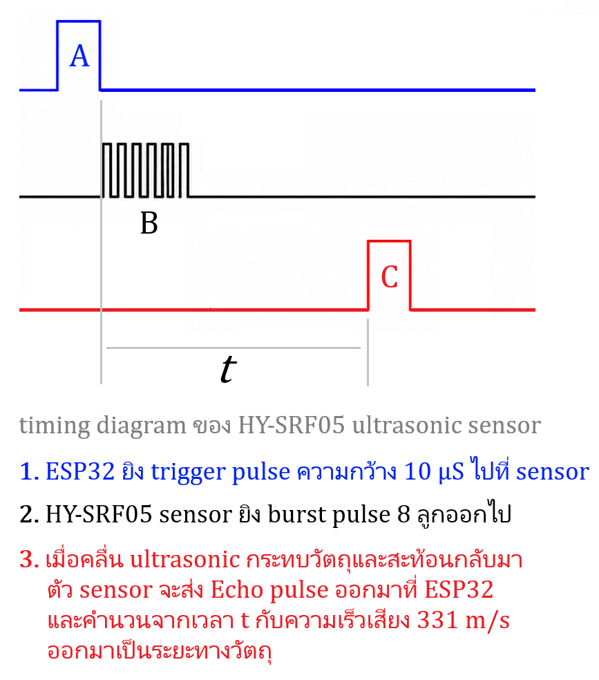
ถึงแม้ Timing diagram จะดูซับซ้อนยุ่งยาก แต่เวลาให้ AI เขียน code เราไม่ต้องบอกรายละเอียดพวกนี้เลยครับ เพราะ AI ถูก train ข้อมูลพวกนี้มาหมดแล้ว มันสามารถออก code ที่สอดคล้องกับ timing diagram นี้แบบเป๊ะเลย ใน prompt เราแค่ระบุให้ชัดว่าขา TRIG , Echo ต่อกับ GPIO ใดของ ESP32
ตัวอย่าง project วัดระยะทาง + LDR วัดความสว่างแสดงค่าแสงเป็น 0 – 100%
ESP32 code ของ project นี้
#include <Wire.h>
#include <Adafruit_GFX.h>
#include <Adafruit_SH110X.h>
#include <DHT.h>

// OLED Configuration
#define SCREEN_WIDTH 128
#define SCREEN_HEIGHT 64
#define OLED_ADDRESS 0x3C  // Common I2C address for these displays
#define I2C_SDA 40
#define I2C_SCL 42
Adafruit_SH1106G display = Adafruit_SH1106G(SCREEN_WIDTH, SCREEN_HEIGHT, &Wire, -1);

// DHT22 Configuration
#define DHTPIN 5
#define DHTTYPE DHT22
DHT dht(DHTPIN, DHTTYPE);

// LDR Configuration
#define LDR_PIN 1

// HY-SRF05 Configuration
#define TRIG_PIN 7
#define ECHO_PIN 8

// Timing Variables (Non-blocking using millis)
unsigned long lastDHTRead = 0;
unsigned long lastLDRRead = 0;
unsigned long lastSonicRead = 0;

const long dhtInterval = 5000;   // 5 seconds
const long ldrInterval = 300;    // 300 ms
const long sonicInterval = 1000; // 1 second

// Global variables to hold last read values
float currentTemp = 0.0;
float lightPercent = 0.0;
float currentRange = 0.0;

void setup() {
  Serial.begin(115200);

  // Initialize Custom I2C pins for ESP32-S3
  Wire.begin(I2C_SDA, I2C_SCL);

  // Initialize OLED
  if (!display.begin(OLED_ADDRESS, true)) {
    Serial.println(F("SH1106 OLED initialization failed!"));
    for (;;);
  }

  display.clearDisplay();
  display.setTextSize(1);
  display.setTextColor(SH110X_WHITE);
  display.display();

  // Initialize DHT
  dht.begin();

  // Initialize Ultrasonic Pins
  pinMode(TRIG_PIN, OUTPUT);
  pinMode(ECHO_PIN, INPUT);

  // Configure ADC attenuation if needed for 0-3V range
  // By default, ESP32 Arduino Core 3.x configures ADC to 11dB (~0V - 3.3V)
  analogSetPinAttenuation(LDR_PIN, ADC_11db);
}

void loop() {
  unsigned long currentMillis = millis();
  bool needUpdateDisplay = false;

  // 1. Read DHT22 every 5 seconds
  if (currentMillis - lastDHTRead >= dhtInterval) {
    lastDHTRead = currentMillis;
    float t = dht.readTemperature();
    if (!isnan(t)) {
      currentTemp = t;
      needUpdateDisplay = true;
    }
  }

  // 2 & 3. Read LDR every 300 ms and map voltage
  if (currentMillis - lastLDRRead >= ldrInterval) {
    lastLDRRead = currentMillis;

    // Read raw ADC (ESP32-S3 has 12-bit ADC: 0 - 4095)
    int rawADC = analogRead(LDR_PIN);

    // Convert to Voltage (assuming 3.3V VREF)
    float voltage = (rawADC / 4095.0) * 3.3;

    // Map 1.0V - 3.0V to 0% - 100%
    if (voltage < 1.0) {
      lightPercent = 0.0;
    } else if (voltage > 3.0) {
      lightPercent = 100.0;
    } else {
      // Linear interpolation formula: (value - in_min) * (out_max - out_min) / (in_max - in_min) + out_min
      lightPercent = (voltage - 1.0) * (100.0 - 0.0) / (3.0 - 1.0) + 0.0;
    }
    needUpdateDisplay = true;
  }

  // 4. Read HY-SRF05 Ultrasonic every 1 second
  if (currentMillis - lastSonicRead >= sonicInterval) {
    lastSonicRead = currentMillis;

    // Trigger the sensor
    digitalWrite(TRIG_PIN, LOW);
    delayMicroseconds(2);
    digitalWrite(TRIG_PIN, HIGH);
    delayMicroseconds(10);
    digitalWrite(TRIG_PIN, LOW);

    // Read echo duration (travel time in microseconds)
    long duration = pulseIn(ECHO_PIN, HIGH, 30000); // 30ms timeout (~5 meters max)

    // Calculate distance in cm (Speed of sound is ~343 m/s or 0.0343 cm/us)
    if (duration > 0) {
      currentRange = (duration * 0.0343) / 2.0;
    } else {
      currentRange = -1.0; // Out of range / timeout indicator
    }
    needUpdateDisplay = true;
  }

  // Update OLED if any data has changed
  if (needUpdateDisplay) {
    updateOLED();
  }
}

void updateOLED() {
  display.clearDisplay();

  // Line 1: Temperature
  display.setCursor(0, 4);
  display.print("Temp: ");
  display.print(currentTemp, 1); // 1 decimal place
  display.print(" C");

  // Line 2: Light Level
  display.setCursor(0, 24);
  display.print("Light level = ");
  display.print(lightPercent, 1); // 1 decimal place
  display.print(" %");

  // Line 3: Range
  display.setCursor(0, 44);
  if (currentRange >= 0) {
    display.print("Range = ");
    display.print(currentRange, 1); // 1 decimal place
    display.print(" cm");
  } else {
    display.print("Range = Out of Bound");
  }

  display.display();
}
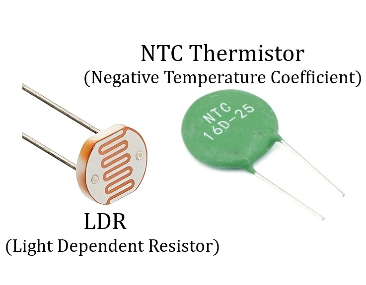
ต่อไปเป็น sensor ความสว่างของแสงก็คือ LDR (Light Dependent Resistor) ตัว LDR นี้มีมาตั้งแต่ยุคก่อนไมโครคอนโทรลเลอร์อีกครับ มันเป็นตัวความต้านทานที่เปลี่ยนค่าได้ตามความเข้มของแสง รุ่นที่นิยมใช้ก็จะมีหน้าตาแบบในภาพนี้ตัวเล็กเท่าหัวเข็มหมุดเท่านั้น เมื่อแสงจ้ามากความต้านทานจะลดลงเหลือประมาณ 1 kΩ และเมื่อมืดเกือบสนิทความต้านทานจะเพิ่มขึ้นไปสูงถึงระดับ 100 -200 kΩ ครับ
ความรู้พื้นฐานทางด้านอิเล็กทรอนิกส์ที่ต้องใช้กับ LDR ก็คือวงจรแบ่งแรงดัน (Voltage divider) ก็คือเราจะต้องต่อ LDR กับตัวความต้านทาน 1 ตัวตามวงจรด้านล่างนี้ ส่วน R จะใช้ค่าเท่าไหร่ก็ขึ้นอยู่กับว่าระดับแสงที่เราต้องการวัดหรือตรวจจับมีความสอดคล้องกับความต้านทานของ LDR ที่เปลี่ยนไปมากน้อยเท่าใด ซึ่งค่าความเข้มแสงก็สามารถแสดงผลได้หลายอย่างกับขึ้นอยู่กับ code ที่เราจะเขียนครับ อย่างเช่นความสว่างระดับ 0 ถึง 100% หรืออาจจะแปลงเทียบเป็นความสว่างหน่วย Lux ก็ได้
ภาพวงจร voltage divider + LDR + NTC กับการต่อเข้า GPIO ของ ESP32
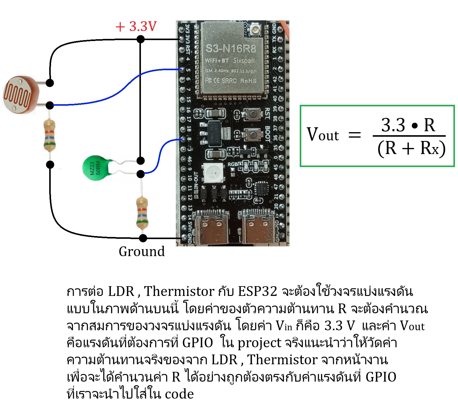
กรณีของ LDR , Thermistor (NTC) ผมจะขออธิบายลงลึกในเรื่องของวิศวกรรมและคณิตศาสตร์หน่อยนึง เนื่องจากผมตั้งใจจะเขียนบทความให้ลงลึกในทฤษฎีเพื่อที่จะสามารถออกแบบ project เองได้
การแปลงความสว่างไปเป็นหน่วย Lux ด้วย LDR
ขอเริ่มที่กราฟความต้านทานของ LDR ก่อน
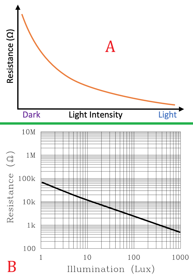
จากภาพบน ค่าความต้านทาน LDR เปลี่ยนแปลงไม่เป็นเชิงเส้นกับความสว่างของแสง (A ในภาพ) ดังนั้นจากการเปลี่ยนแปลงที่ไม่เป็นเชิงเส้นทำให้คำนวณง่าย ๆ ไม่ได้ เราจะต้องทำดังนี้ ….
🛑 ดึง raw data ความต้านทาน vs ความสว่างออกมาจากกราฟใน datasheet (B ในภาพ) ซึ่งงานแบบนี้ AI ถนัดมาก เพียงแค่โยนภาพกราฟนี้เข้า AI ก็จะได้ตัวเลข raw data ของภาพทั้งหมด
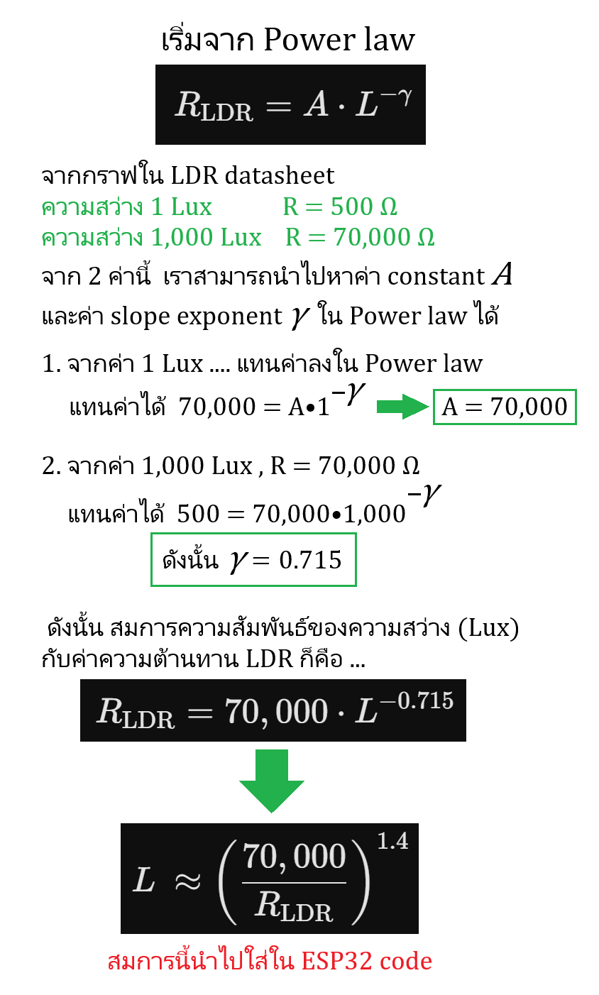
🛑 ความสัมพันธ์ที่ไม่เป็นเชิงเส้นระหว่างค่าความต้านทานกับค่าความสว่างจะต้องใช้ Power law เพื่อหาสมการระหว่างค่าความต้านทานกับค่าความสว่าง (Lux) …. รายละเอียดการคำนวณตามภาพล่าง
sensor ตัวต่อไปก็คือ Thermistor หรืออีกชื่อคือ NTC (Negative Temperature Coefficient) ตัวนี้มันจะเป็นตัวความต้านทานที่เปลี่ยนไปตามอุณหภูมิครับ ซึ่ง Negative Temperature Coefficient หมายความว่าค่าความต้านทาน NTC จะลดลงเมื่ออุณหภูมิเพิ่ม Thermistor ต้องใช้กับวงจรแบ่งแรงดันแบบเดียวกับ LDR และมันไม่ได้ให้ค่าอุณหภูมิแบบเบ็ดเสร็จสมบูรณ์เหมือนกับ sensor DHT22 ที่กล่าวไปด้านบน เราต้องทำการวัดค่าความต้านทานของ Thermistor เทียบกับอุณหภูมิที่เราจะใช้ในงานนั้น ๆ โดยเฉพาะ และออกแบบวงจรแบ่งแรงดันเพื่อให้แรงดันที่จะเข้า GPIO มีความเหมาะสมกับ code ที่เราเขียน
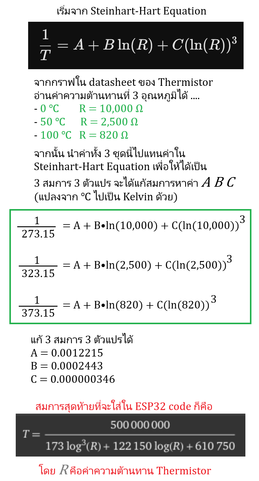
ในการใช้ Thermistor เพื่อแสดงค่าเป็น ℃ สมการจะมีความแตกต่างจาก LDR เนื่องจากค่าความต้านทานกับความร้อนของมันแปรผกผันและไม่เป็นเชิงเส้น และในทางคณิตศาสตร์แล้วการเปลี่ยนแปลงของอุณหภูมิ – ความต้านทานจะแตกต่างจาก Power law ดังนั้นจึงต้องใช้สมการหนึ่งซึ่งทำงานได้ดีกับการแปรผกผันและไม่เป็นเชิงเส้น ก็คือสมการ Steinhart-Hart Equation
การคำนวณก็เริ่มจากใช้กราฟจาก datasheet ของ Thermistor จากเช่นเคยครับโดยนำกราฟมาหาค่าความต้านทานใน 3 ช่วงอุณหภูมิ อย่างของโปรเจคนี้ตั้งใจจะให้วัดในช่วง 0 – 100 ℃ ดังนั้นจึงเอาค่าความต้านทานที่ 0 50 และ 100 ℃ จากกราฟมาคิด และเมื่อแทนค่าลงใน Steinhart-Hart Equation แล้วก็จะได้เป็นค่า A B C รายละเอียดตามภาพครับ
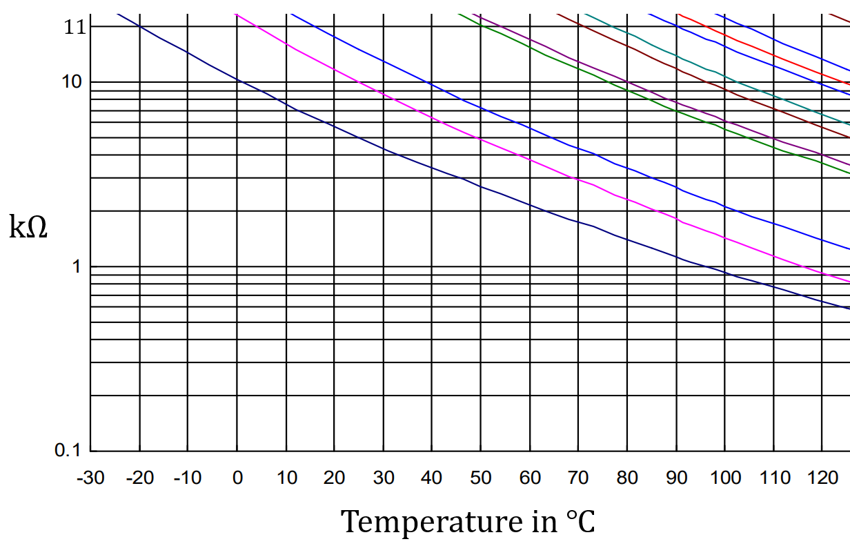
ตัวอย่าง project LDR , Thermistor แสดงถึงค่าความต้านทานของ LDR , Thermistor ที่เปลี่ยนไปตามความสว่างและอุณหภูมิ
ESP32 code ของ project นี้
// Pin Definitions
const int LED_1 = 11;      // Controlled by GPIO 7 voltage
const int LED_2 = 13;      // Controlled by GPIO 8 voltage
const int ANALOG_PIN_1 = 7;
const int ANALOG_PIN_2 = 8;

// Voltage Thresholds
const float THRESHOLD_1 = 2.8;
const float THRESHOLD_2 = 2.5;

// Timing Constants
const unsigned long READ_INTERVAL = 300;  // 0.3 seconds in milliseconds
const unsigned long FLASH_INTERVAL = 100; // 5 Hz means 5 full cycles per second (100ms ON, 100ms OFF)

// Timing Variables
unsigned long lastReadTime = 0;
unsigned long lastFlashTime = 0;

// LED States
bool led1Flashing = false;
bool led2Flashing = false;
bool flashState = false;

// ESP32-S3 ADC Configuration
// By default, attenuation is set to 11dB (on Core v3.x), allowing a range of 0V to ~3.3V.
// The ADC resolution is 12-bit (0 to 4095).
const float ADC_VREF = 3.3;
const int ADC_MAX_VALUE = 4095;

void setup() {
  Serial.begin(115200);

  // Configure LED pins as outputs
  pinMode(LED_1, OUTPUT);
  pinMode(LED_2, OUTPUT);

  // Ensure LEDs start turned off
  digitalWrite(LED_1, LOW);
  digitalWrite(LED_2, LOW);

  // Configure ADC resolution
  analogReadResolution(12);
}

void loop() {
  unsigned long currentMillis = millis();

  // Task 1: Read Voltages every 0.3 seconds (300 ms)
  if (currentMillis - lastReadTime >= READ_INTERVAL) {
    lastReadTime = currentMillis;

    // Read raw ADC values
    int raw1 = analogRead(ANALOG_PIN_1);
    int raw2 = analogRead(ANALOG_PIN_2);

    // Convert raw values to voltage
    float voltage1 = (raw1 * ADC_VREF) / ADC_MAX_VALUE;
    float voltage2 = (raw2 * ADC_VREF) / ADC_MAX_VALUE;

    // Print to Serial Monitor for debugging
    Serial.printf("GPIO 7: %.2f V | GPIO 8: %.2f V\n", voltage1, voltage2);

    // Check thresholds to enable/disable flashing flags
    led1Flashing = (voltage1 >= THRESHOLD_1);
    led2Flashing = (voltage2 >= THRESHOLD_2);
  }

  // Task 2: Handle 5 Hz Flashing (Toggles state every 100 ms)
  if (currentMillis - lastFlashTime >= FLASH_INTERVAL) {
    lastFlashTime = currentMillis;
    flashState = !flashState; // Invert the common flash state flag

    // Handle LED 1 (GPIO 11)
    if (led1Flashing) {
      digitalWrite(LED_1, flashState);
    } else {
      digitalWrite(LED_1, LOW); // Force off if below threshold
    }

    // Handle LED 2 (GPIO 13)
    if (led2Flashing) {
      digitalWrite(LED_2, flashState);
    } else {
      digitalWrite(LED_2, LOW); // Force off if below threshold
    }
  }
}
ตัวอย่าง project LDR , Thermistor แสดงค่าความสว่างเป็น Lux และอุณหภูมิเป็น ℃
ESP32 code ของ project นี้
#include <SPI.h>
#include <Wire.h>
#include <Adafruit_GFX.h>
#include <Adafruit_SH110X.h>

// --- Pin Allocations ---
#define LDR_PIN 1          // LDR Divider Input
#define NTC_PIN 5          // NTC Divider Input
#define I2C_SDA 40         // Custom I2C Data Pin
#define I2C_SCL 42         // Custom I2C Clock Pin

// --- Hardware Parameter Constants ---
#define VCC 3.38           // Supply Voltage as specified
#define LDR_RF 4700.0      // Fixed Resistor for LDR divider (4.7k)
#define NTC_RF 3300.0      // Optimized Fixed Resistor for NTC divider (3.3k)

// --- Derived Curve Mathematical Parameters ---
#define LDR_A 70000.0
#define LDR_GAMMA 0.715

// Calculated Steinhart-Hart Coefficients for the bottom curve
#define ST_A 0.0012215
#define ST_B 0.0002443
#define ST_C 0.000000346

// --- OLED Display Settings ---
#define SCREEN_ADDRESS 0x3C
Adafruit_SH1106G display = Adafruit_SH1106G(128, 64, &Wire, -1);

void setup() {
  Serial.begin(115200);

  // Initialize custom I2C interface pins for ESP32-S3
  Wire.begin(I2C_SDA, I2C_SCL);

  // Set ADC Resolution to 12-Bit (0-4095 range)
  analogReadResolution(12);

  // Initialize SH1106 Display Panel
  if(!display.begin(SCREEN_ADDRESS, true)) {
    Serial.println(F("SH1106 allocation failed"));
    for(;;);
  }

  display.clearDisplay();
  display.setTextColor(SH110X_WHITE);
  display.display();
}

void loop() {
  // ==========================================
  // 1. ASYNCHRONOUS LDR LUX CALCULATION
  // ==========================================
  int ldrAdc = analogRead(LDR_PIN);
  if (ldrAdc <= 0) ldrAdc = 1;
  if (ldrAdc >= 4095) ldrAdc = 4094;

  // Linearize to ADC Voltage Scale (~3.1V Internal Max Reference)
  float ldrVolt = (float)ldrAdc * (3.1 / 4095.0);
  float ldrResistance = LDR_RF * ((VCC / ldrVolt) - 1.0);
  float lux = pow((LDR_A / ldrResistance), (1.0 / LDR_GAMMA));

  // Limit bounds safety clamp
  if(lux < 0) lux = 0;

  // ==========================================
  // 2. ASYNCHRONOUS NTC TEMPERATURE CALCULATION
  // ==========================================
  int ntcAdc = analogRead(NTC_PIN);
  if (ntcAdc <= 0) ntcAdc = 1;
  if (ntcAdc >= 4095) ntcAdc = 4094;

  float ntcVolt = (float)ntcAdc * (3.1 / 4095.0);
  float ntcResistance = NTC_RF * ((VCC / ntcVolt) - 1.0);

  // Steinhart-Hart Implementation
  float logR = log(ntcResistance);
  float steinhartK = 1.0 / (ST_A + (ST_B * logR) + (ST_C * logR * logR * logR));
  float tempCelsius = steinhartK - 273.15;

  // ==========================================
  // 3. OLED MONITOR UPDATE RENDERING
  // ==========================================
  display.clearDisplay();

  // // Line 1: Temperature Reading (Decreased to Text Size 1)
  display.setTextSize(1);
  display.setCursor(0, 4); // Kept near the top
  display.print("Temp = ");
  display.print(tempCelsius, 1);
  display.print(" C");

  // Line 2: Illumination Level Reading (Decreased to Text Size 1)
  // Adjusted the cursors so the text flows tightly together on a smaller scale
  display.setCursor(0, 24);
  display.print("Brightness is =");
  display.setCursor(0, 36);
  display.print((int)lux);
  display.print(" Lux");

  display.display();

  // 1-second background refresh iteration delay
  delay(1000);
}