ESP32 (EP.5) ESP32 กับงาน PWM

วันนี้จะขอเสนอการใช้งาน ESP32 ในงาน PWM …. PWM ย่อมาจาก Pulse Width Modulation มันคือการกำเนิดลูกคลื่นสี่เหลี่ยมในความถี่ต่าง ๆ และสามารถเปลี่ยนแปลงค่าของ % duty cycle ได้  การกำเนิด PWM แบบนี้มีประโยชน์หลายงานแล้วแต่งานที่เราต้องการจะทำครับ  โดยหลักเลยก็คือการควบคุมความเร็วของมอเตอร์แบบ BLDC และยังสามารถใช้ในการควบคุมความสว่างของหลอดไฟขนาดเล็กอย่างเช่น LED ได้ด้วยการป้อน PWM เข้าไปใน LED ด้วย duty cycle ที่เปลี่ยนแปลงระหว่างช่วง 10 – 90% ซึ่งจะทำให้ LED สว่างน้อยถึงมาก

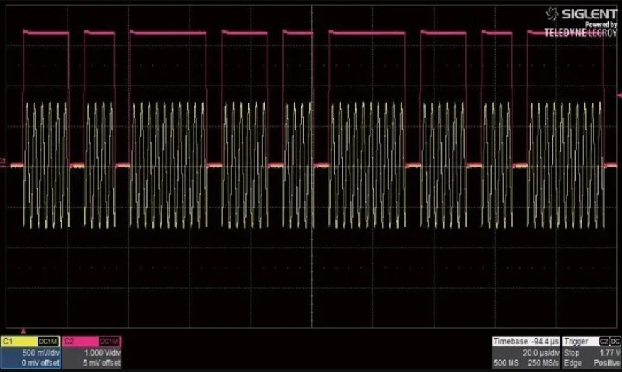
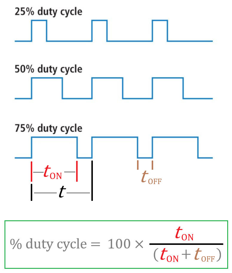
ก่อนอื่นมาดูลักษณะของรูปคลื่น PWM ก่อนว่าลักษณะของ duty cycle ว่ามันจะเป็นอย่างไร  จากภาพนี้จะเห็นว่ารูปคลื่นสี่เหลี่ยมจะมีความกว้างช่วง ON และ OFF ใน 1 ช่วงคลื่น  ถ้าช่วง ON มีค่าน้อยก็หมายความว่า % ของ duty cycle มีค่าต่ำ  และหากช่วง ON กว้างและช่วง OFF แคบนิดเดียวก็คือรูปคลื่นนั้นมี % ของ duty cycle สูงครับ


ใน ESP32 จะมี hardware ที่ทำหน้าที่กำเนิด PWM โดยเฉพาะ  นั่นก็หมายความว่าในการกำเนิด PWM จะไม่กินกำลัง CPU ของ ESP32 เลยเพราะมันเป็น dedicated hardware ซึ่งจะแบ่งเป็น 2 ส่วนก็คือ
🛑  LEDC (LED Controller)  เป็นส่วนของ hardware ที่ออกแบบสำหรับใช้งานแบบ basic สามารถนำไปคุมความสว่างของ LED ก็ได้ หรือกำเนิดคลื่นสี่เหลี่ยมเพื่อใช้งานอเนกประสงค์ใด ๆ ก็ได้โดยสามารถปรับ duty cycle ได้อย่างอิสระ  อย่างในโปรเจคที่ผมจะสาธิตด้านล่างนี้สามารถกำเนิดได้กว้างมากถึง 5 Hz – 1 MHz และปรับ duty cycle ได้กว้างในช่วง 5 – 95% โดยทำงานผ่าน web dashboard

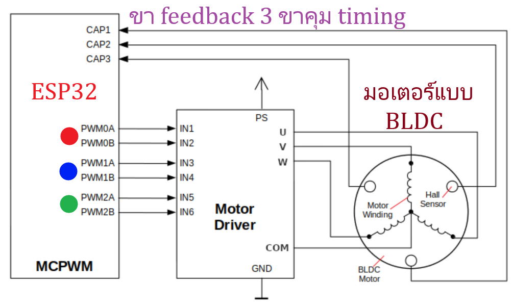
🛑 MCPWM (Motor Control Pulse Width Modulator)  ส่วนนี้จะทำงานค่อนข้างซับซ้อนเนื่องจากออกแบบให้ควบคุมมอเตอร์แบบ 3 เฟส  ดังนั้นจึงให้ output ได้ถึง 3 ชุดและมีขารองรับการป้อนกลับจากตัวมอเตอร์เพื่อสร้าง timing ที่แม่นยำ


ต่อไปจะว่าด้วยข้อจำกัดของในการกำเนิด PWM …. เนื่องจาก ESP32 ทำงานด้วยสัญญาณนาฬิกา clock ความถี่ 80 MHz จาก APB (Advanced Peripheral Bus)  ดังนั้นจึงมีข้อจำกัดอยู่เล็กน้อยในการกำเนิดที่ความถี่สูงระดับ 1 MHz หรือประมาณนี้  สิ่งที่ว่านี้ก็คือ Resolution ของ duty cycle

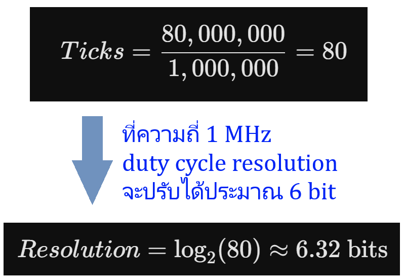
จาก clock 80 MHz ของ ESP32 เมื่อ LEDC ทำงานภายในตัวจะมี counter ภายใน  หากเรากำหนดให้สร้างความถี่ 1 MHz  ตัว counter ของ LEDC ก็จะสามารถนับได้เท่ากับ 80 ticks ซึ่งจำนวน 80 ticks ที่นับได้นี้ค่าของ resolution ก็จะมีค่าประมาณ 6 bit  ตามสมการ log นี้

และหากเรากำเนิดที่ความถี่ต่ำกว่านี้อย่างเช่น 40 KHz  ค่า resolution ก็จะประมาณ 10 bit

ค่า resolution ที่เป็นจำนวน bit นี้มันหมายความถึง step ของ duty cycle ที่สามารถทำได้ อย่างที่ความถี่ 1 MHz = resolution เท่ากับ 6 bit  ดังนั้น steps ของค่า duty cycle ที่จะเปลี่ยนแปลงได้ก็จะ = 26 = 64 steps  ก็คือ duty cycle 0 – 100% จะเริ่มต้นจาก (100/64) = 1.5625% → 3.125 → 4.6875  6.25  7.8125  9.375 …. 50  51.5625 ไปจนถึง 98.4375 %

และหากที่ความถี่ต่ำกว่านี้เช่น 40 KHz  ค่า resolution ก็จะประมาณ 10 bit และหาความถี่ต่ำลงไปอีกก็จะสามารถปรับ step ของ duty cycle ได้อย่างละเอียดมากกว่านี้อีกแต่ก็สูงสุดก็คือ 16 bit ครับ  0.09765625 → 0.1953125 → 0.29296875 → 0.390625 …. ซึ่งละเอียดมาก

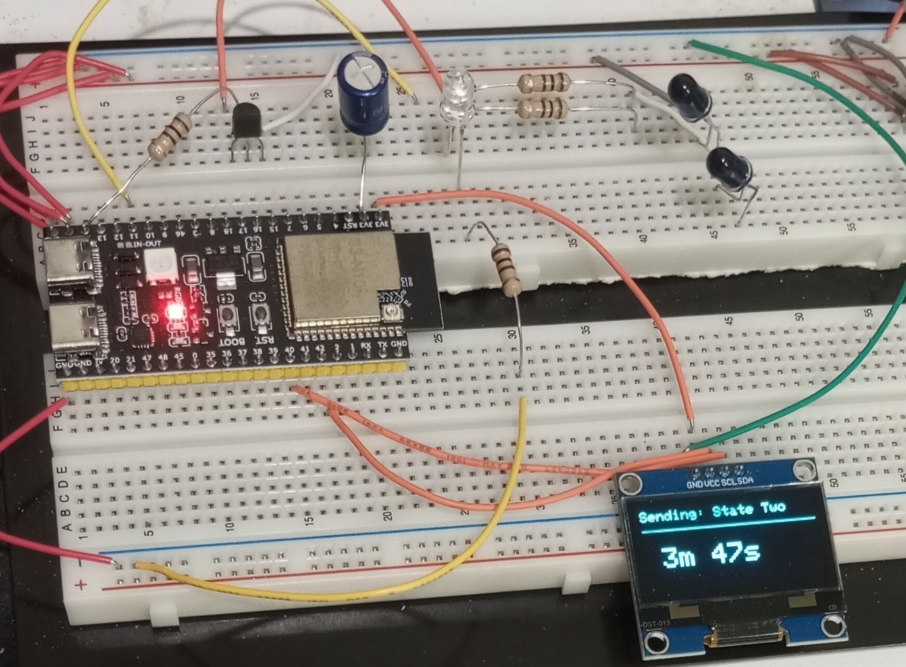
ในคลิปที่ท่านเห็นด้านล่างนี้คือไฟวิ่งที่ออกแบบให้การวิ่งของ LED 5 ดวงนี้เป็นไปแบบ smooth fade นั่นก็คือใช้ PWM มาช่วยครับ โดยเปลี่ยนจากการกระพริบธรรมดาคือเปลี่ยนจาก logic 1 และ 0 ของ GPIO ให้เป็นกำเนิด PWM ออกมาจาก GPIO ทั้ง 5 ขา โดยในช่วงการเปลี่ยนการวิ่งระหว่าง LED แต่ละดวงก็ป้อน PWM ที่มี duty cycle เปลี่ยนแปลงระหว่าง 10 – 90% ทำให้ลักษณะของไฟวิ่งจะดูนุ่มนวลอย่างที่เห็นครับ


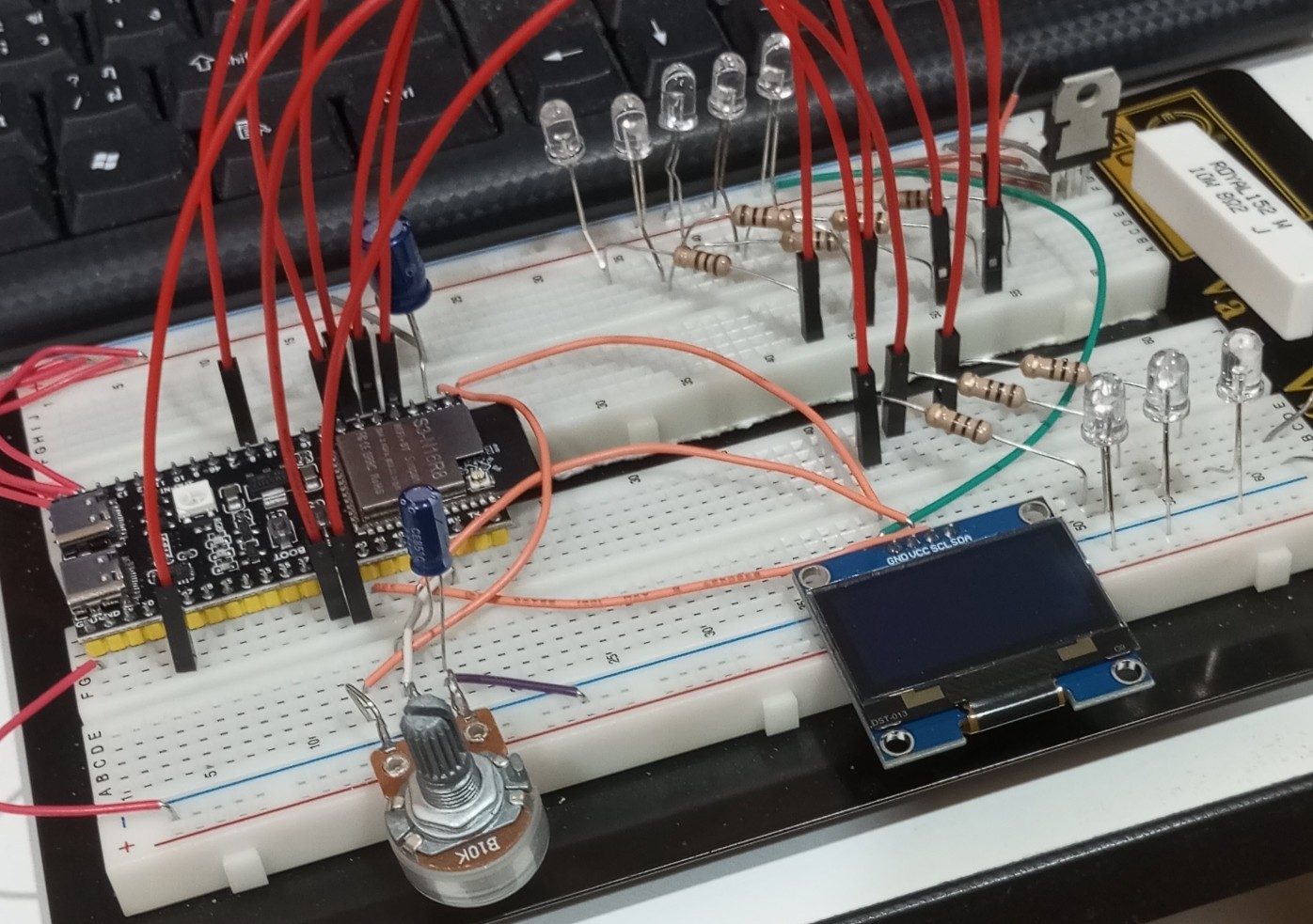
อุปกรณ์ที่ใช้มีเพียงเท่านี้

Code ทั้งหมดของไฟวิ่ง PWM

// Define Pins for both groups
const int pinsGroupA[] = {21, 38, 39}; // 3 LEDs (Simple ON/OFF running)
const int numGroupA = 3;

const int pinsGroupB[] = {4, 5, 6, 7, 8}; // 5 LEDs (Smooth PWM Fading)
const int numGroupB = 5;

const int potPin = 1;

// PWM Settings for ESP32-S3 (Core 3.x)
const int pwmFreq = 5000;       // 5 kHz PWM frequency
const int pwmResolution = 8;    // 8-bit resolution (0 - 255 brightness)
const int maxBrightness = 255;

// State Machine States
enum RunState {
  MODE_THREE_LEDS,
  MODE_FIVE_LEDS
};
RunState currentState = MODE_THREE_LEDS;

// Sequencer Variables
int currentLedIdx = 0;
int previousLedIdx = -1;
int cycleCount = 0;

unsigned long lastRunMillis = 0;
unsigned long lastFadeMillis = 0;
const int fadeInterval = 5; // Update fade every 5ms
float fadeProgress = 0.0;

void setup() {
  // Initialize Group A (3 LEDs) as standard digital outputs
  for (int i = 0; i < numGroupA; i++) {
    pinMode(pinsGroupA[i], OUTPUT);
    digitalWrite(pinsGroupA[i], LOW);
  }

  // Initialize Group B (5 LEDs) using the Core 3.x PWM API
  for (int i = 0; i < numGroupB; i++) {
    ledcAttach(pinsGroupB[i], pwmFreq, pwmResolution);
    ledcWrite(pinsGroupB[i], 0);
  }
  
  analogReadResolution(12); // 12-bit ADC (0-4095)
}

void loop() {
  unsigned long currentMillis = millis();

  // --- STATE 1: 3 LEDs Running at Fixed 3 Hz ---
  if (currentState == MODE_THREE_LEDS) {
    unsigned long runIntervalA = 1000 / 3; // Fixed 3 Hz frequency -> ~333ms per step

    if (currentMillis - lastRunMillis >= runIntervalA) {
      lastRunMillis = currentMillis;

      // Turn off previous LED
      if (previousLedIdx != -1) {
        digitalWrite(pinsGroupA[previousLedIdx], LOW);
      }
      
      // Turn on current LED
      digitalWrite(pinsGroupA[currentLedIdx], HIGH);

      // Track sequencing indices
      previousLedIdx = currentLedIdx;
      currentLedIdx++;

      // Check if one full cycle of 3 LEDs is complete
      if (currentLedIdx >= numGroupA) {
        currentLedIdx = 0;
        cycleCount++;

        // If 3 complete cycles are reached, reset and switch state
        if (cycleCount >= 3) {
          // Clean up Group A states
          digitalWrite(pinsGroupA[previousLedIdx], LOW);
         
          // Switch to Group B
          currentState = MODE_FIVE_LEDS;
          cycleCount = 0;
          currentLedIdx = 0;
          previousLedIdx = numGroupB - 1; // Prepare fading index for Group B
          fadeProgress = 0.0;
        }
      }
    }
  }

  // --- STATE 2: 5 LEDs Running with Smooth Fade + Variable POT Speed ---
  else if (currentState == MODE_FIVE_LEDS) {
    // Read POT to calculate variable frequency (1Hz to 5Hz)
    int potValue = analogRead(potPin);
    float frequency = map(potValue, 0, 4095, 100, 500) / 100.0;
    unsigned long runIntervalB = 1000 / frequency; // Dynamic step time based on frequency

    // A. Handle Smooth Fading Calculations (Every 5ms)
    if (currentMillis - lastFadeMillis >= fadeInterval) {
      lastFadeMillis = currentMillis;

      unsigned long timePassed = currentMillis - lastRunMillis;
      fadeProgress = (float)timePassed / (float)runIntervalB;
      if (fadeProgress > 1.0) fadeProgress = 1.0;

      int fadeInDuty = fadeProgress * maxBrightness;
      int fadeOutDuty = (1.0 - fadeProgress) * maxBrightness;

      // Apply smooth PWM fading to current and previous LEDs
      ledcWrite(pinsGroupB[currentLedIdx], fadeInDuty);
      ledcWrite(pinsGroupB[previousLedIdx], fadeOutDuty);
    }

    // B. Handle stepping to the next LED in Group B
    if (currentMillis - lastRunMillis >= runIntervalB) {
      lastRunMillis = currentMillis;

      // Ensure clean final values for step transition
      ledcWrite(pinsGroupB[previousLedIdx], 0);
      ledcWrite(pinsGroupB[currentLedIdx], maxBrightness);

      previousLedIdx = currentLedIdx;
      currentLedIdx++;

      // Check if one full cycle of 5 LEDs is complete
      if (currentLedIdx >= numGroupB) {
        currentLedIdx = 0;
        cycleCount++;

        // If 3 complete cycles are reached, reset and switch state back to Group A
        if (cycleCount >= 3) {
          // Clean up Group B states
          ledcWrite(pinsGroupB[previousLedIdx], 0);

          // Switch to Group A
          currentState = MODE_THREE_LEDS;
          cycleCount = 0;
          currentLedIdx = 0;
          previousLedIdx = -1; // Reset to safe initial value for Group A
        }
      }
      
      fadeProgress = 0.0; // Reset fade progress for the new step
    }
  }
}

ต่อไปคือ project จริงที่ใช้ประโยชน์สูงสุดจากของ PWM โดยออกแบบให้กำเนิดความถี่ในช่วงกว้างมากระหว่าง 5 Hz – 1 MHz และสามารถปรับ duty cycle ได้ช่วงกว้างระหว่าง 5 – 95% ครับและเพื่อความสะดวกก็ออกแบบให้รับค่าความถี่และ duty cycle จาก web dashboard ได้เลยดูรายละเอียดในคลิปครับ


Code ทั้งหมดของ PWM generator + web dashboard

#include <WiFi.h>
#include <WebServer.h>

// --- WiFi Credentials ---
const char* ssid = " SSID ของ Wi-Fi ท่าน";
const char* password = " password ของ Wi-Fi ท่าน ";

// --- Hardware Settings ---
const uint8_t PWM_PIN = 11;
uint32_t currentFreq = 1000; // Default 1 kHz
uint8_t currentDuty = 50;    // Default 50%

WebServer server(80);

// --- HTML/CSS/JS Dashboard ---
// Stored in program memory (PROGMEM) to save RAM
const char index_html[] PROGMEM = R"rawliteral(
<!DOCTYPE html>
<html>
<head>
  <meta name="viewport" content="width=device-width, initial-scale=1">
  <title>ESP32-S3 PWM Controller</title>
  <style>
    body { font-family: Arial, sans-serif; text-align: center; background-color: #f4f4f9; padding: 20px; }
    .card { background: white; padding: 30px; border-radius: 10px; box-shadow: 0 4px 8px rgba(0,0,0,0.1); display: inline-block; max-width: 100%; overflow-x: hidden; }
    h2 { color: #333; }
    .slider-container { margin: 30px 0; }
    input[type=range] { width: 100%; max-width: 400px; }
    
    /* PC Specific styling: 1200px wide sliders */
    @media (min-width: 1024px) {
      input[type=range] { width: 1200px; max-width: 1200px; }
      .card { max-width: 1300px; }
    }
    slider
    .value-label { font-size: 1.2em; font-weight: bold; color: #0066cc; }
    input[type=number] { padding: 10px; font-size: 1em; width: 150px; text-align: center; border: 1px solid #ccc; border-radius: 5px; }
    button { padding: 10px 20px; font-size: 1em; background-color: #0066cc; color: white; border: none; border-radius: 5px; cursor: pointer; }
    button:hover { background-color: #004c99; }
  </style>
</head>
<body>
  <div class="card">
    <h2>ESP32-S3 PWM Dashboard</h2>
    
    <div class="slider-container">
      <h3>Frequency (Hz)</h3>
      <input type="range" id="freqSlider" min="1" max="1000000" value="1000" oninput="updateFreqFromSlider()">
      <br><br>
      <input type="number" id="freqInput" min="1" max="1000000" value="1000" oninput="updateFreqFromInput()">
      <button onclick="executeSend()">Send</button>
    </div>

    <hr>

    <div class="slider-container">
      <h3>Duty Cycle (%)</h3>
      <input type="range" id="dutySlider" min="5" max="95" step="5" value="50" oninput="onDutySlide()">
      <p class="value-label"><span id="dutyLabel">50</span>%</p>
    </div>
  </div>

  <script>
    let canSend = true;

    // Sync input box when slider moves and throttle network request
    function updateFreqFromSlider() {
      document.getElementById("freqInput").value = document.getElementById("freqSlider").value;
      throttleSend();
    }

    // Sync slider when input box changes (User types value)
    function updateFreqFromInput() {
      let val = document.getElementById("freqInput").value;
      // Clamp values between 1 and 1,000,000
      if(val < 1) val = 1;
      if(val > 1000000) val = 1000000;
      document.getElementById("freqSlider").value = val;
    }

    // Update duty label and throttle network request
    function onDutySlide() {
      document.getElementById("dutyLabel").innerText = document.getElementById("dutySlider").value;
      throttleSend();
    }

    // Ensures we only send HTTP GET every 1 second maximum while sliding
    function throttleSend() {
      if(canSend) {
        executeSend();
        canSend = false;
        setTimeout(() => { canSend = true; }, 1000); // 1000ms = 1 second
      }
    }

    // The actual HTTP GET request
    function executeSend() {
      let f = document.getElementById("freqInput").value;
      let d = document.getElementById("dutySlider").value;
      
      fetch(`/update?freq=${f}&duty=${d}`)
        .then(response => { console.log("PWM Updated"); })
        .catch(error => { console.error("Error updating PWM", error); });
    }
  </script>
</body>
</html>
)rawliteral";

// --- Function to update hardware PWM based on ESP32 Core v3.x API ---
void setPWM(uint32_t freq, uint8_t dutyPercent) {
  // 1. Calculate the maximum bit resolution for this frequency
  uint8_t resolution = log2(80000000 / freq);
  
  // Clamp resolution to a maximum of 14 bits for stability, and minimum of 1 bit
  if (resolution > 14) resolution = 14;
  if (resolution < 1) resolution = 1;

  // 2. THE FIX: Update frequency dynamically
  // ledcChangeFrequency returns 0 if the pin hasn't been attached yet.
  // So if it fails (like during the first run in setup()), we use ledcAttach instead.
  if (ledcChangeFrequency(PWM_PIN, freq, resolution) == 0) {
    ledcAttach(PWM_PIN, freq, resolution);
  }

  // 3. Convert the percentage (5-95%) into the raw hardware value based on resolution
  uint32_t max_duty_value = (1 << resolution) - 1;
  uint32_t raw_duty = (dutyPercent * max_duty_value) / 100;

  // 4. Write the value to the hardware
  ledcWrite(PWM_PIN, raw_duty);
  
  Serial.printf("Set PWM -> Freq: %d Hz | Duty: %d%% | Res: %d-bit | Raw Duty: %d/%d\n",
                freq, dutyPercent, resolution, raw_duty, max_duty_value);
}

void setup() {
  Serial.begin(115200);
  ledcSetClockSource(LEDC_USE_APB_CLK);
  // Initialize PWM with default values
  setPWM(currentFreq, currentDuty);

  // Connect to Wi-Fi
  Serial.print("Connecting to WiFi: ");
  Serial.println(ssid);
  WiFi.mode(WIFI_STA);
  WiFi.begin(ssid, password);
  
  while (WiFi.status() != WL_CONNECTED) {
    delay(500);
    Serial.print(".");
  }
  Serial.println("\nWiFi Connected!");
  Serial.print("IP Address: ");
  Serial.println(WiFi.localIP());

  // --- Web Server Routes ---
  
  // 1. Serve the Dashboard
  server.on("/", []() {
    server.send(200, "text/html", index_html);
  });

  // 2. Handle the HTTP GET request from JS (e.g. /update?freq=500000&duty=45)
  server.on("/update", []() {
    if (server.hasArg("freq") && server.hasArg("duty")) {
      currentFreq = server.arg("freq").toInt();
      currentDuty = server.arg("duty").toInt();
      
      // Safety clamps
      if(currentFreq < 1) currentFreq = 1;
      if(currentFreq > 1000000) currentFreq = 1000000;
      if(currentDuty < 5) currentDuty = 5;
      if(currentDuty > 95) currentDuty = 95;

      setPWM(currentFreq, currentDuty);
      server.send(200, "text/plain", "OK");
    } else {
      server.send(400, "text/plain", "Missing parameters");
    }
  });

  server.begin();
  Serial.println("HTTP server started");
}

void loop() {
  // Listen for incoming web requests
  server.handleClient();
}

ทำไมของทอดจึงหอมอร่อยจัง ?

ถ้าหากเอาแบบวิทยาศาสตร์เลยก็ต้องพูดถึง Maillard Reaction  มันเป็นปฏิกิริยาเคมีที่เมื่อบรรดาสารประกอบไนโตรเจน กรดอะมิโนและน้ำตาลถูกความร้อนสูงจากการ “ทอด” (150 – 170 ℃) จัดเรียงโครงสร้างใหม่ และพวก volatile aromatic compounds จะกลายเป็นไอออกมาเยอะมาก …. ซึ่งก็คือ “กลิ่น” อันยั่วยวนเรานั่นเอง 😂😁

Maillard Reaction ยังทำให้เกิดรสชาติใหม่หลากหลาย + เพิ่มความเข้มข้นของรส “อูมามิ”  นี่เองทำให้ของทอดอร่อยถูกใจ  พวกของทอดทั้งหลาย ถึงแม้จะเป็นวัตถุดิบราคาถูก อย่างไส้กรอกแป้งไม้ละ 5 บาท10 บาทก็หอมทั้งนั้นเนื่องจาก Maillard Reaction

ปฏิกิริยาเคมี  Maillard Reaction ที่สร้างความหอมอร่อยที่ว่านี้ไม่จำเป็นต้องทอดอย่างเดียว นำไปอบก็เกิดได้ ขอเพียงแค่มีอุณหภูมิในช่วง 150 – 170 ℃ อาหารก็สามารถเกิดปฏิกิริยานี้ได้ นี่เองเป็นเหตุผลที่ว่าอาหารประเภทต้มหรือนึ่งไม่เคยมีความหอมอร่อย เพราะปฏิกิริยานี้ไม่เกิดครับ (อาหารประเภท “ต้ม” จะมีความหอมน่ากินด้วยเครื่องเทศแทนครับ แต่ไม่ได้หอมจากปฏิกิริยานี้มันเกิดจากสารประกอบที่ระเหยง่ายในบรรดาเครื่องเทศระเหยออกมาจากการต้ม)


ส่วนน้ำมันจะมีผลน้อยครับ หรือจะว่าความหอมอร่อยไม่ได้มาจากน้ำมันซักเท่าไหร่ แต่เกิดจากปฏิกิริยาเคมีนี้ทั้งสิ้น …. “น้ำมัน” จะเพิ่มความหอมอร่อยได้ชัดเจนคือใช้น้ำมันหมูทำกับข้าว อย่างเช่น ผัดกะเพราบ้าน ๆ นี่แหละ ถ้าใช้น้ำมันหมูแบบที่เจียวจากมันหมูมันจะมีความหอมแบบประหลาด เพิ่มความอร่อยทวีคูณ

ถ้าเป็นการทำอาหารในเชิงอุตสาหกรรมหรือร้านอาหาร/ภัตตาคารใหญ่ เขาจะมีสิ่งที่เรียกว่า Lard   มันคือผลิตภัณฑ์ไขมันสีขาวกึ่งแข็งที่ได้จากการแปรรูปเนื้อเยื่อไขมันของหมู

หากทำกินเองก็เจียวจากมันหมูนี่แหละที่สุดแล้ว


เห็นภาพไก่ทอด …. ขอพูดถึงไก่ KFC สูตรดั้งเดิมหน่อย  ก็คือที่ KFC เรียกกันว่า “สูตรผู้พัน

สูตรผู้พันเนี่ยผมกินมาตลอด 30 ปี ไม่เคยเปลี่ยนเลย ไม่เคยสั่งสูตรไก่กรอบฮอตสไปซี่อะไรทั้งนั้น กินแต่สูตรผู้พันอย่างเดียวเนื่องจากเครื่องเทศครบมาเต็ม …. ครั้งต่อไปหากท่านไปกิน KFC ลองสั่งสูตรผู้พันดูนะแล้วจะติดใจในความหอมเครื่องเทศ

ESP32 (EP.4) ESP32 กับ dashboard + แจ้งเตือนผ่าน Line

จะขอเสนอการนำ ESP32 ไปใช้งานกับ web dashboard บน server จริง และมี feature ที่สำคัญก็คือ Line messaging API (แจ้งเตือนผ่าน Line)

การใช้งานกับ web dashboard บน server จริงคือการประยุกต์ใช้งานแบบ IoT เต็มตัวครับ ภาพรวมของการใช้งานแบบนี้ก็คือ ESP32 จะรับ data จาก sensor ต่าง ๆ และต่อ GPIO ออกไปเพื่อควบคุมอุปกรณ์ / เครื่องใช้ไฟฟ้าในบ้าน  และในฝั่งปลายทาง PC / Notebook / มือถือของเรา) ก็จะเป็น web dashboard ซึ่งสามารถดูข้อมูลหรือสถานะของ sensor หรือระบบรักษาความปลอดภัยที่บ้านผ่าน web dashboard นอกจากดูก็สามารถกดปุ่มสั่งงานเครื่องใช้ไฟฟ้า/อุปกรณ์ใด ๆ ที่บ้านเราได้ นี่คือการใช้งานในลักษณะ IoT เต็มตัว

สิ่งที่ต้องมี 2 อย่าง
🛑 อย่างแรกคือเว็บไซต์ส่วนตัว
การใช้งาน IoT ได้แบบคล่องตัวมากที่สุดสิ่งที่ต้องมีเลยก็คือเว็บไซต์ส่วนตัวของเรา ซึ่งในปัจจุบันนี้การจะจดทะเบียน Domain name + เช่า web hosting บอกได้เลยว่าราคาต่อปีไม่ถึง 1,000 บาทก็มีครับ ถูกสุดที่ผมเคยเห็นประมาณ 850 บาทก็ได้แล้ว ดังนั้นจึงขอแนะนำอย่างยิ่งสำหรับท่านที่ต้องการเรียนรู้การทำ IoT project หรือจะฝึกฝีมือกับ ESP32 เพื่อใช้งาน IoT เต็มรูปแบบก็ควรสมัครเว็บไซต์ส่วนตัวไว้

อีกประเภทหนึ่งที่นิยมกันมากก็คือ “Cloud IoT” อย่างเช่น ThingsBoard , Adafruit IO , Blynk , Thinger.io , ThingSpeak  มันคือแพลตฟอร์มที่ใช้ได้ฟรีสามารถแสดง dashboard ได้และแทบไม่ต้องใช้ code เลย ลักษณะการสร้าง dashboard + เชื่อมข้อมูลกับ ESP32 ของเราจะเป็นการ “ลากแล้ววาง” แต่ผมคิดว่ามันใช้งานไม่ค่อยยืดหยุ่นสักเท่าไหร่ / ปรับแต่งเองได้ไม่เต็มที่และที่สำคัญก็คือใช้กับ Line messaging API ได้ยาก

🛑 อย่างที่สองคือ Line messaging API
Line messaging API ที่จะใช้งานในโปรเจคอย่างกระทู้นี้ ทุกคนก็สามารถสมัครได้ฟรีโดยใช้งานได้ 300 ข้อความต่อเดือนซึ่งก็ถือว่าเหลือเฟือในการใช้งานเพื่อทดลองและเรียนรู้ครับ …. การใช้ Line messaging API จะต้องสมัคร LINE Official Account ก่อน … เริ่มที่นี่ครับ
https://manager.line.biz/
ดูวิธีการสมัครที่นี่
(คลิปจากช่อง ครูอภิวัฒน์ “สอนสร้างสื่อ”
https://www.youtube.com/@KruApiwat


เมื่อสมัคร LINE Official Account เสร็จแล้วก็ไป enable messaging API …. และเมื่อทุกอย่างเรียบร้อยแล้วทั้ง 4 ภาพด้านล่างนี้คือข้อมูล 2 ส่วนที่จะต้องใช้ไปใส่ใน ESP32 code ครับ


ต่อไปคือสถาปัตยกรรมในระบบ IoT ทั่วไป (ซึ่ง project นี้ก็ใช้แบบนี้)

จากภาพบนนี้  ESP32 ที่บ้านหรือที่ทำงานเราก็ทำหน้าที่เป็นเพียง client เพื่อที่จะส่ง-รับข้อมูลเข้าระหว่าง web server  ในส่วนของ web server ก็จะเป็นที่เก็บ dashboard + database ซึ่ง database ไม่ต้องยุ่งยากเป็นแบบ SQL เลยครับ ใช้แบบ text file database (JSON) ก็ใช้งานได้ดีเพียงพอแล้วกับ sensor 2 – 3 ตัวและการเก็บข้อมูลประมาณ 1 สัปดาห์ต่อเนื่องกัน


ใน project ที่ผมจะสาธิตให้ดูในกระทู้นี้หน้าตาของ web dashboard ก็คือตามภาพล่างครับ  

ผมต่อ sensor ไว้ 2 ตัวก็คือ DHT22 กับ LDR เพื่อแสดงค่าอุณหภูมิและความสว่างของแสงแสดงเป็นกราฟทุก 1 นาทีและได้รวมระบบ Line messaging API ไว้ด้วย  โดยใน Code กำหนดให้ส่งข้อความแจ้งเตือนเมื่อมีการเปิดประตูและแสงสว่างมีค่าต่ำกว่าที่กำหนดไว้ครับ

นี่คือภาพของอุปกรณ์ที่ใช้มีเพียงเท่านี้ ก็คือมี sensor 2 ตัวเท่านั้น

และในภาพนี้สังเกตจุดสีแดงกับน้ำเงินกระพริบอยู่ก็คือเป็นสาย jumper 2 เส้นที่ผมใช้แทน switch จำลองการเปิดประตูด้านหน้าและด้านหลังส่งข้อมูลไปยังเว็บ server เพื่อส่งข้อความเข้า LINE ในมือถือเมื่อประตูถูกเปิดหรือเมื่อความสว่างของแสงน้อยกว่าที่กำหนดครับ


คลิบนี้แสดงถึงการแจ้งเตือนผ่าน Line

Code ทั้งหมด

/*
   ESP32-S3 N16R8 Data Logger & Monitor (Core 3.3.1)
   Hardware Connections:
   - DHT22 Data Pin: GPIO 5 (needs 10k pull-up resistor to 3.3V)
   - LDR/Voltage Sensor: GPIO 1 (Analog input ADC1_CH0)
   - Front Door Sensor: GPIO 7 (Logic input with internal pull-up)
   - Back Door Sensor: GPIO 8 (Logic input with internal pull-up)
*/

#include <WiFi.h>
#include <HTTPClient.h>
#include <WiFiClientSecure.h>
#include <DHT.h>

// Wi-Fi Credentials
const char* ssid     = "NT91124G";
const char* password = "911928TOT";

// API Endpoints & Credentials
const char* serverUrl = "https://www.navy007.com/temp32/data_receiver.php";
const char* lineApiUrl = "https://api.line.me/v2/bot/message/push";
const char* lineToken  = " Line Token ของท่าน "; 
const char* lineUserId = " User ID ของท่าน ";

// Pins
#define DHTPIN 5
#define DHTTYPE DHT22
#define VOLT_PIN 1
#define DOOR_FRONT_PIN 7
#define DOOR_BACK_PIN 8

DHT dht(DHTPIN, DHTTYPE);

// Timers (Non-blocking)
unsigned long lastDHTSend = 0;
unsigned long lastSensorRead = 0;
const unsigned long dhtInterval = 60000;   // 1 minute
const unsigned long sensorInterval = 5000; // 5 seconds

// State tracking for LINE Spam Prevention
enum LightState { DARK, PARTLY_CLOUD, STRONG_SUN };
LightState currentLightState = STRONG_SUN; 
bool isFirstLightRead = true;

int lastFrontDoorState = -1; 
int lastBackDoorState = -1;

// Float definitions for tracking current values
float currentTemperature = 0.0;
float currentHumidity = 0.0;
float currentVoltGPIO1 = 0.0;

void setup() {
  Serial.begin(115200);
  
  // Setup Sensor Pins
  dht.begin();
  pinMode(VOLT_PIN, INPUT); // ADC1_CH0 (GPIO 1 is safe for ADC)
  pinMode(DOOR_FRONT_PIN, INPUT_PULLUP);
  pinMode(DOOR_BACK_PIN, INPUT_PULLUP);
  
  // Setup Wi-Fi
  WiFi.begin(ssid, password);
  Serial.print("Connecting to Wi-Fi");
  while (WiFi.status() != WL_CONNECTED) {
    delay(500);
    Serial.print(".");
  }
  Serial.println("\nConnected to Wi-Fi Network!");
}

void loop() {
  unsigned long currentMillis = millis();

  // Task 1: Pull DHT22 Data every 1 minute
  if (currentMillis - lastDHTSend >= dhtInterval) {
    lastDHTSend = currentMillis;
    readDHT22();
    sendDataToServer();
  }

  // Task 2 & 3: Monitor GPIO 1, 7, and 8 every 5 seconds
  if (currentMillis - lastSensorRead >= sensorInterval) {
    lastSensorRead = currentMillis;
    monitorPins();
  }
}

void readDHT22() {
  float temp = dht.readTemperature();
  float hum = dht.readHumidity();
  if (!isnan(temp) && !isnan(hum)) {
    currentTemperature = temp;
    currentHumidity = hum;
    Serial.printf("DHT22 - Temp: %.2f C, Hum: %.2f%%\n", temp, hum);
  } else {
    Serial.println("Error reading from DHT22");
  }
}

void monitorPins() {
  // --- GPIO 1 Voltage Monitoring ---
  // ESP32-S3 ADC has 12-bit resolution (0-4095) spanning ~3.1V depending on calibration
  int rawADC = analogRead(VOLT_PIN);
  currentVoltGPIO1 = (rawADC / 4095.0) * 3.3; // Estimated voltage scale

  LightState computedState;
  if (currentVoltGPIO1 < 2.0) {
    computedState = DARK;
  } else if (currentVoltGPIO1 >= 2.0 && currentVoltGPIO1 <= 2.35) {
    computedState = PARTLY_CLOUD;
  } else {
    computedState = STRONG_SUN;
  }

  // Handle state change for light sensor to prevent spamming
  if (computedState != currentLightState || isFirstLightRead) {
    currentLightState = computedState;
    isFirstLightRead = false;
    
    if (currentLightState == DARK) {
      sendLineMessage("ระดับแสงต่ำเกินไป");
    }
  }

  // --- GPIO 7 (Front Door) & GPIO 8 (Back Door) Monitoring ---
  int frontDoor = digitalRead(DOOR_FRONT_PIN);
  int backDoor = digitalRead(DOOR_BACK_PIN);

  // Spam prevention check for front door
  if (frontDoor != lastFrontDoorState) {
    lastFrontDoorState = frontDoor;
    if (frontDoor == HIGH) { // Logic 1 = Open
      sendLineMessage("ประตูหน้าเปิด");
    }
  }

  // Spam prevention check for back door
  if (backDoor != lastBackDoorState) {
    lastBackDoorState = backDoor;
    if (backDoor == HIGH) { // Logic 1 = Open
      sendLineMessage("ประตูหลังเปิด");
    }
  }

  Serial.printf("GPIO1: %.2f V, Front: %d, Back: %d\n", currentVoltGPIO1, frontDoor, backDoor);
}

// Function to Send Official LINE Push Notification
void sendLineMessage(String message) {
  if (WiFi.status() != WL_CONNECTED) return;

  WiFiClientSecure client;
  client.setInsecure(); // Required for share hosting or API calls where cert pinning isn't hardcoded
  HTTPClient http;

  http.begin(client, lineApiUrl);
  http.addHeader("Content-Type", "application/json");
  http.addHeader("Authorization", "Bearer " + String(lineToken));

  // Construct official LINE Push Message JSON
  String jsonPayload = "{\"to\":\"" + String(lineUserId) + "\",\"messages\":[{\"type\":\"text\",\"text\":\"" + message + "\"}]}";

  int httpResponseCode = http.POST(jsonPayload);
  if (httpResponseCode > 0) {
    Serial.println("LINE Push Sent successfully: " + String(httpResponseCode));
  } else {
    Serial.println(String("Error sending LINE Push: ") + http.errorToString(httpResponseCode).c_str());
  }
  http.end();
}

// Push latest telemetry to the Apache Share Hosting Server
void sendDataToServer() {
  if (WiFi.status() != WL_CONNECTED) return;

  WiFiClientSecure client;
  client.setInsecure();
  HTTPClient http;

  http.begin(client, serverUrl);
  http.addHeader("Content-Type", "application/x-www-form-urlencoded");

  // Format POST payload
  String postData = "temp=" + String(currentTemperature, 2) +
                    "&volt=" + String(currentVoltGPIO1, 2) +
                    "&front_door=" + String(lastFrontDoorState) +
                    "&back_door=" + String(lastBackDoorState);

  int httpResponseCode = http.POST(postData);
  if (httpResponseCode > 0) {
    Serial.println("Telemetry synced: " + String(httpResponseCode));
  } else {
    Serial.println(String("Error syncing telemetry: ") + http.errorToString(httpResponseCode).c_str());
  }
  http.end();
}