ESP32 (EP.8) ESP32 ควบคุมอุปกรณ์ไฟฟ้าในห้อง

วันนี้จะขอเสนอเรื่องการใช้งานประยุกต์ใช้ ESP32 กับรีโมทคอนโทรลในการควบคุมอุปกรณ์ไฟฟ้าในห้อง

การใช้งาน ESP32 ในการควบคุมอุปกรณ์ไฟฟ้าต่าง ๆ ในห้องจะมีความสะดวกมาก  เนื่องจาก ESP32 มีขา GPIO จำนวนมาก (สูงสุดถึงประมาณ 15 ขาในการใช้งานแบบ digital ON/OFF)  และรีโมท 1 อันก็จะมีทั้งแป้นตัวเลขและปุ่มอื่นจำนวนมากเช่นกัน  นั่นก็หมายความว่าเราสามารถควบคุมอุปกรณ์ได้นับสิบอย่างที่มีในห้องโดยที่เรานั่งอยู่กับโต๊ะหรือนอนอยู่บนเตียงก็ได้ครับ

project นี้ค่อนข้างจะง่ายมาก …. ขั้นตอนจะมี 2 อย่างเท่านั้น

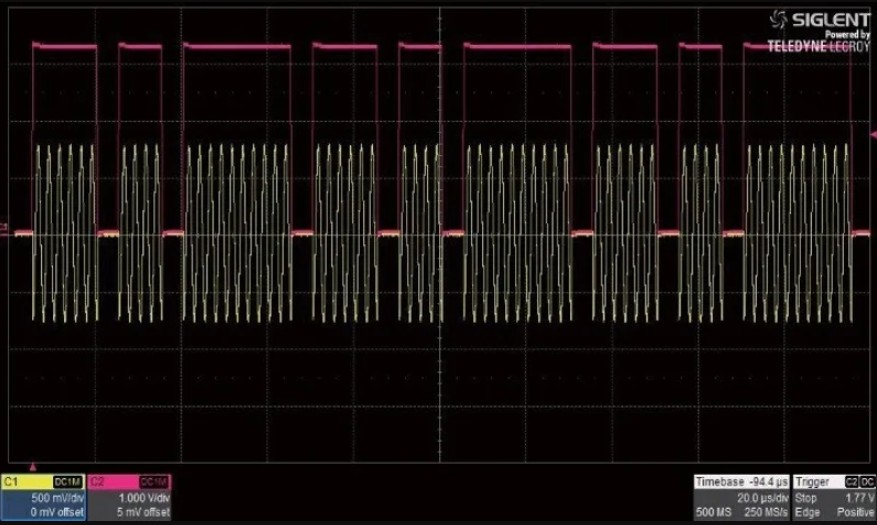
ขั้นแรกก็คือเราจะต้องหา code ที่ตัวรีโมทคอนโทรลส่งสัญญาณ Infrared ออกมาก่อน  ซึ่งสัญญาณ infrared ที่รีโมทส่งออกมาจะเป็น pulse train แบบภาพนี้

ซึ่งก็แน่นอนว่าทุกปุ่มของรีโมทคอนโทรลจะมี code ต่างกัน  ลักษณะของ code นี้เมื่อรับโดย ESP32 มันจะแปลง pulse train ที่ซับซ้อนออกมาเป็นชุด data ในรูปแบบ HEX (Hexadecimal numbers) จะต้องทำงานร่วมกับ library ครับ …. ซึ่ง library ใหม่สุดที่แนะนำก็คือ “IRremote” library (พัฒนาโดย shirriff / z3t0 / ArminJo)  ตัวล่าสุดนี้ทำงานได้ดีและให้ HEX data สั้นที่สุด  ดูได้จากคลิปด้านล่างนี้เลยครับ

จากคลิปนี้จะเห็นว่าเมื่อเรากดปุ่มตัวเลข 1 2 3 และอื่น ๆ มันจะให้ HEX data ที่สั้นมาก  เราก็เอา HEX data นี้ไปใส่ใน code ของ ESP32 เพื่อที่จะสั่งงาน GPIO ให้ ON / OFF ตามปุ่มของรีโมทที่เรากดได้

Code ทั้งหมด

#include <Arduino.h>
#include <IRremote.hpp>

// Hardware Pin Definitions
const int IR_RECEIVE_PIN = 15;
const int PIN_BTN1 = 21;
const int PIN_BTN2 = 38;
const int PIN_BTN3 = 39;
const int PIN_BTN4 = 47;
const int PIN_BUZZER = 4;

// Captured IR Raw Data Constants
const uint32_t IR_BTN_1 = 0x7308CF;
const uint32_t IR_BTN_2 = 0xB304CF;
const uint32_t IR_BTN_3 = 0x330CCF;
const uint32_t IR_BTN_4 = 0xD302CF;

// Variables to track output states
bool statePin21 = LOW;
bool statePin38 = LOW;
bool statePin39 = LOW;
bool statePin47 = LOW;

// Non-blocking Buzzer Timing Variables
bool buzzerActive = false;
unsigned long buzzerStartTime = 0;
const unsigned long BUZZER_DURATION = 200; // 0.5 second beep duration

void setup() {
  Serial.begin(115200);

  // Initialize GPIO outputs
  pinMode(PIN_BTN1, OUTPUT);
  pinMode(PIN_BTN2, OUTPUT);
  pinMode(PIN_BTN3, OUTPUT);
  pinMode(PIN_BTN4, OUTPUT);
  pinMode(PIN_BUZZER, OUTPUT);

  digitalWrite(PIN_BTN1, LOW);
  digitalWrite(PIN_BTN2, LOW);
  digitalWrite(PIN_BTN3, LOW);
  digitalWrite(PIN_BTN4, LOW);
  digitalWrite(PIN_BUZZER, LOW);

  // Initialize IR Receiver
  IrReceiver.begin(IR_RECEIVE_PIN, ENABLE_LED_FEEDBACK);
  Serial.println("ESP32-S3 IR Control System Ready.");
}

void loop() {
  // 1. Process Incoming IR Commands
  if (IrReceiver.decode()) {
    // Ignore repeat hold signals to prevent accidental fast toggling
    if (!(IrReceiver.decodedIRData.flags & IRDATA_FLAGS_IS_REPEAT)) {
      uint32_t rawData = IrReceiver.decodedIRData.decodedRawData;

      // Trigger Buzzer for 0.5 sec upon receiving any IR command
      digitalWrite(PIN_BUZZER, HIGH);
      buzzerActive = true;
      buzzerStartTime = millis();

      switch (rawData) {
        case IR_BTN_1:
          statePin21 = !statePin21;
          digitalWrite(PIN_BTN1, statePin21);
          Serial.print("Button 1 pressed -> GPIO 21 state: ");
          Serial.println(statePin21 ? "ON" : "OFF");
          break;

        case IR_BTN_2:
          statePin38 = !statePin38;
          digitalWrite(PIN_BTN2, statePin38);
          Serial.print("Button 2 pressed -> GPIO 38 state: ");
          Serial.println(statePin38 ? "ON" : "OFF");
          break;

        case IR_BTN_3:
          statePin39 = !statePin39;
          digitalWrite(PIN_BTN3, statePin39);
          Serial.print("Button 3 pressed -> GPIO 39 state: ");
          Serial.println(statePin39 ? "ON" : "OFF");
          break;

        case IR_BTN_4:
          statePin47 = !statePin47;
          digitalWrite(PIN_BTN4, statePin47);
          Serial.print("Button 4 pressed -> GPIO 47 state: ");
          Serial.println(statePin47 ? "ON" : "OFF");
          break;

        default:
          // Unmapped IR codes
          break;
      }
    }

    IrReceiver.resume(); // Enable receiving the next signal
  }

  // 2. Non-blocking Buzzer Timer (turns OFF active buzzer after 500ms)
  if (buzzerActive && (millis() - buzzerStartTime >= BUZZER_DURATION)) {
    digitalWrite(PIN_BUZZER, LOW);
    buzzerActive = false;
  }
}

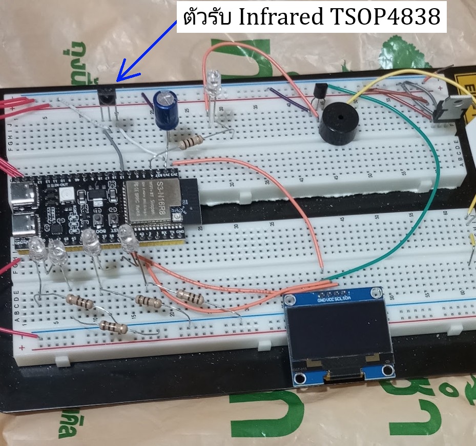
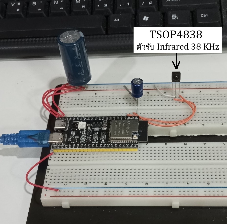
อุปกรณ์ที่ใช้มีเพียงเท่านี้  

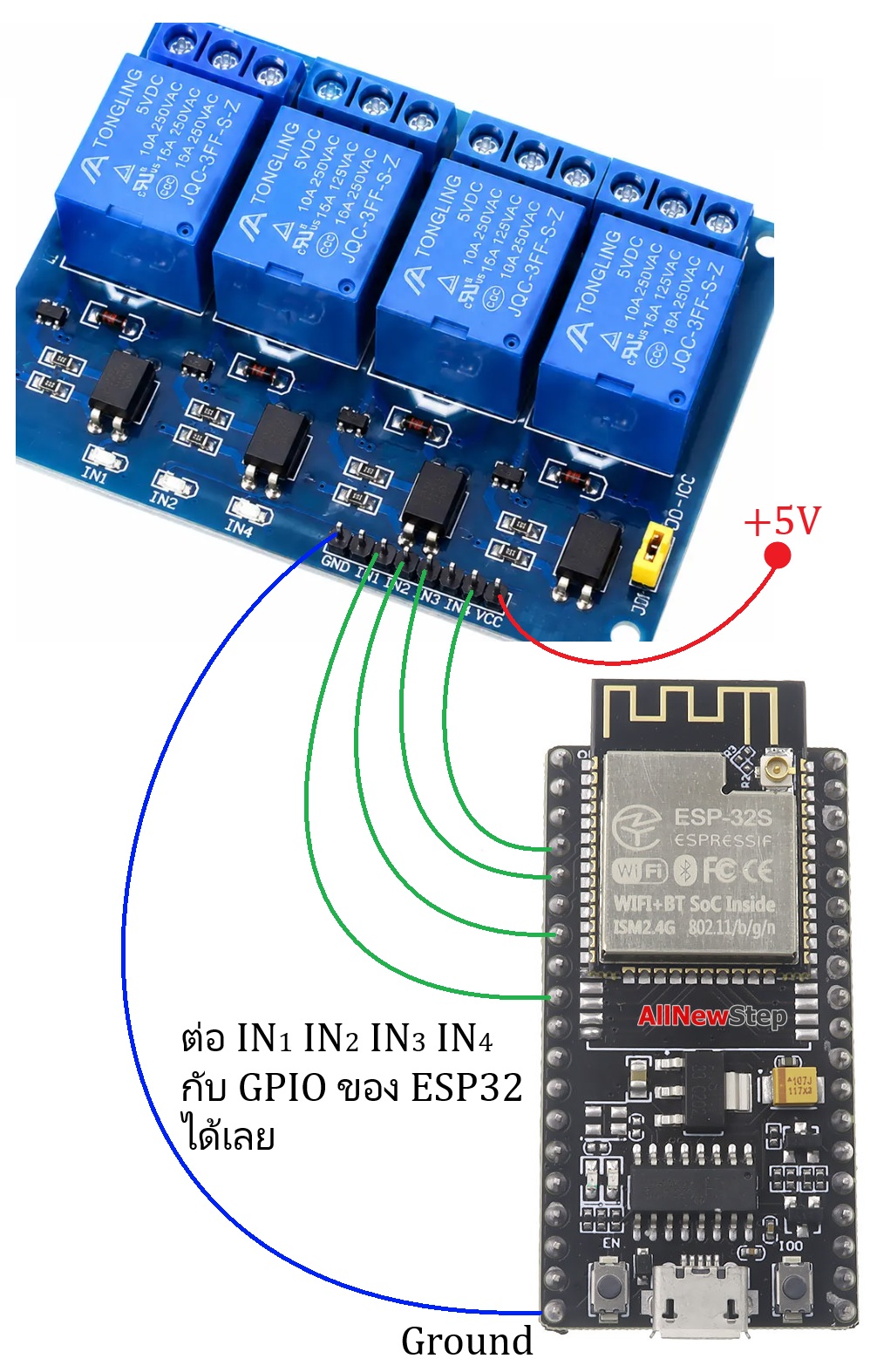
LED 4 ดวงในภาพต่ออยู่กับ GPIO ของ ESP32 …. ซึ่งในการประยุกต์ใช้งานจริงเราจะต้องต่อวงจรจาก GPIO ต่าง ๆ เพื่อไปควบคุมอุปกรณ์ซึ่งใช้ไฟ 220 โวลต์  วิธีการต่อที่ง่ายที่สุดก็คือใช้ครับรายละเอียดตามภาพด้านล่าง

ในการหา HEX data ของแต่ละปุ่มในการกดรีโมท  อุปกรณ์ที่ใช้มีเพียงเท่านี้

Code ทั้งหมด

#include <Arduino.h>
#include <IRremote.hpp>

// Define the GPIO pin where your IR receiver module (e.g., VS1838B) OUT pin is connected
const int IR_RECEIVE_PIN = 15; 

void setup() {
  // Initialize Serial communication at 115200 baud
  Serial.begin(115200);
  while (!Serial) delay(10); // Wait for Serial to open

  Serial.println("\n--- ESP32 IR Code Scanner ---");
  Serial.println("Point your remote at the receiver and press any button...\n");

  // Start the IR receiver
  // ENABLE_LED_FEEDBACK blinks the ESP32's built-in LED whenever an IR signal is detected
  IrReceiver.begin(IR_RECEIVE_PIN, ENABLE_LED_FEEDBACK);
}

void loop() {
  // Check if an IR signal has been received and decoded
  if (IrReceiver.decode()) {
    
    // Ignore repeat signals (when you hold down a button)
    if (!(IrReceiver.decodedIRData.flags & IRDATA_FLAGS_IS_REPEAT)) {
      
      Serial.print("Protocol: ");
      Serial.print(getProtocolString(IrReceiver.decodedIRData.protocol));
      
      // Print the 8-bit Command in HEX format (Most common for button mapping)
      Serial.print(" | Command (HEX): 0x");
      if (IrReceiver.decodedIRData.command < 0x10) Serial.print("0"); // Leading zero formatting
      Serial.print(IrReceiver.decodedIRData.command, HEX);

      // Print the full Raw Data/Address frame in HEX format for reference
      Serial.print(" | Raw Data: 0x");
      Serial.println(IrReceiver.decodedIRData.decodedRawData, HEX);
    } 
    else {
      Serial.println("[Button Held Down - Repeat Signal]");
    }

    // Prepare the receiver to accept the next IR signal
    IrReceiver.resume(); 
  }
}
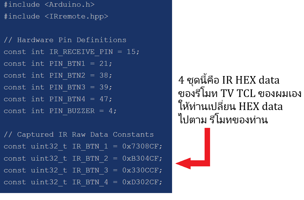
ให้ท่านเปลี่ยน HEX data ตามของรีโมทท่าน

ESP32 (EP.7) ESP32 ทำเป็น RC meter

การใช้ ESP32 ทำเป็น RC meter …. ขอเริ่มที่การวัดค่าความต้านทานก่อน  

พื้นฐานที่ง่ายที่สุดและได้ผลดีมากพอสมควรก็คือการต่อตัวความต้านทานเป็นวงจรแบ่งแรงดัน (Voltage divider)  วงจรแบ่งแรงดันนั้นรายละเอียดของวงจรและสมการที่ใช้เป็นไปตามภาพด้านล่างนี้  

สมการที่ใช้จะไม่ยากเลยเนื่องจากมันก็เป็นกฎของโอห์มธรรมดานี่เองครับ  การประยุกต์ใช้วงจรแบ่งแรงดันเพื่อทำให้วัดค่าความต้านทานได้ก็คือ  ต่อ Vout ของวงจรแบ่งแรงดันกับ GPIO เพื่อวัดค่าแรงดัน  โดยมีแรงดัน Vin นำมาจากไฟ 3.3 โวลต์ของ ESP32 เอง  และ Vout ก็ต่อตรงกับ GPIO ของ ESP32 ใน ADC mode

  ในสมการล่างนี้  ตัวความต้านทานที่เราต้องการจะวัดค่าก็คือตัว R….. ส่วนตัว R2 จะใช้ R ค่าคงที่  ซึ่งจากค่าแรงดัน input อ้างอิง 3.3 โวลต์ค่าของ R2 ที่เหมาะสมก็คือ 22kΩ …. ดังนั้นการหาสมการสุดท้ายที่จะใส่ใน code เราก็จะต้องย้ายข้างสมการ โดยในสมการให้แทนค่าแรงดัน Vin = 3.3 โวลต์และค่าเท่ากับ 22kΩ  สุดท้ายแล้วจะได้สมการที่จะนำไปใส่ใน code ตามภาพด้านล่างนี้


ส่วนการวัดค่า Capacitor วิธีที่ง่ายที่สุดก็คือจะต้องต่อวงจรเพิ่มโดยใช้ IC 555 timer ครับ
จะขออธิบายถึงวงจรสำหรับ IC 555 timer ตัวนี้ก่อน (ภาพล่าง) การต่อ IC 555 ในลักษณะนี้จะเรียกว่า Astable multivibrator  สูตรเพื่อหาความถี่จะมาจากค่าความสัมพันธ์ระหว่างอุปกรณ์ 3 ตัวก็คือ R1 , R2 และ C  ซึ่งสูตรก็ง่ายมากรายละเอียดตามภาพล่าง

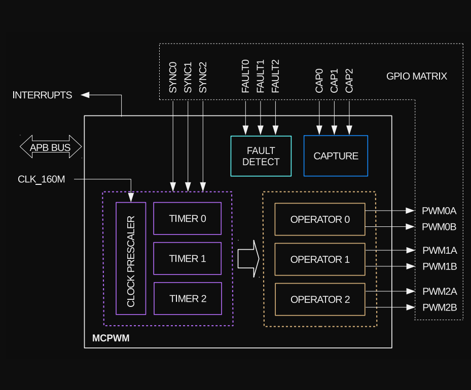
concept การทำงานก็คือ  เมื่อเราจิ้ม capacito rที่ต้องการวัดลงไป  ตัว IC 555 ก็จะกำเนิดความถี่ป้อนเข้า GPIO (digital mode) ของ ESP32 และวัดความถี่ + แปลงไปเป็นค่า Capacitor ที่เราจะวัด  ในการ code ให้วัดค่า capacitor วิธีการที่ดีที่สุดก็คือใช้คุณสมบัติอันแม่นยำอย่างหนึ่งของ MCPWM โดยมันจะวัดคาบเวลาระหว่างของขาขึ้น (Rising edge) ของคลื่นความถี่ที่กำเนิดจาก IC 555 เข้ามาและคำนวณออกมาเป็นค่าของ capacitor เป็นไปตามสมการด้านล่างนี้


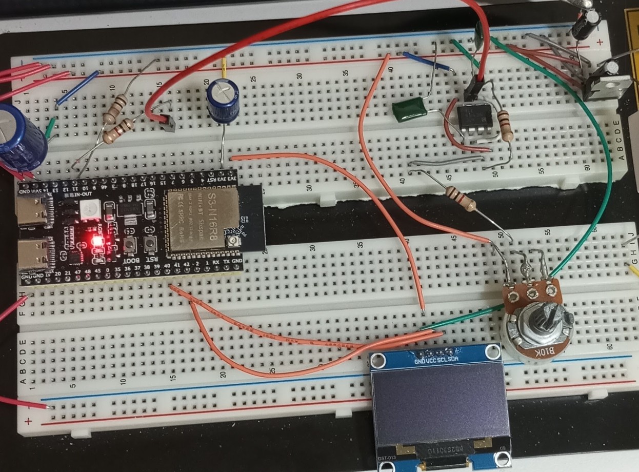
อุปกรณ์ทั้งหมดมีเพียงเท่านี้
จากภาพนี้ ในวงจรส่วนบนก็คือวงจรกำเนิดความถี่ของ IC 555 และสังเกตในจอภาพก็จะแสดงค่า Resistor , Capacitor

ในภาพล่างนี้ เอา capacitor ขนานกัน 2 ตัว (100 µF + 10 µF) ก็จะอ่านได้ค่า capacitance ที่ถูกต้องก็คือ 111.5 µF …. และใช้สาย jumper จิ้มวัด R 5.6kΩ ในจอภาพก็แสดงค่า 5.59 kΩ

Code ทั้งหมด

#include <Arduino.h>
#include <SPI.h>
#include <Wire.h>
#include <Adafruit_GFX.h>
#include <Adafruit_SH110X.h>
#include "driver/mcpwm_cap.h"

// Hardware Pin Definitions
#define CAP_INPUT_PIN   11   // Capacitance input (MCPWM)
#define RES_ANALOG_PIN  1    // Resistance input (ADC1_CH0 / GPIO 1)
#define I2C_SDA         40   // Shared OLED SDA
#define I2C_SCL         42   // Shared OLED SCL
#define SCREEN_ADDRESS  0x3C

// OLED Display Setup
#define SCREEN_WIDTH 128
#define SCREEN_HEIGHT 64
Adafruit_SH1106G display(SCREEN_WIDTH, SCREEN_HEIGHT, &Wire, -1);

// --- Capacitance Meter Constants & Variables ---
const double TIMER_CONSTANT = 1.44 / 3000.0; // 555 Timer Astable Mode (R1=1000, R2=1000)
const uint32_t APB_CLOCK = 80000000;         // 80 MHz MCPWM clock source

volatile uint32_t last_capture_ticks = 0;
volatile uint32_t current_prescaler = 1;
volatile bool new_data_available = false;
volatile uint32_t last_interrupt_time = 0;

mcpwm_cap_channel_handle_t cap_chan = NULL;
mcpwm_cap_timer_handle_t cap_timer = NULL;

// Global variables to store latest measurements
double global_frequency = 0.0;
bool cap_connected = false;

// --- Resistance Meter Constants & Variables ---
unsigned long last_resistor_measure = 0;
const unsigned long resistor_interval = 500; // Measure resistance every 500ms
float global_resistance = -1.0;              // -1.0 indicates "OPEN" or disconnected

// Forward Declarations
String formatWithDigits(long value);
void set_capture_prescaler(uint32_t prescale_val);

// --- Capacitance MCPWM ISR Callback ---
static bool IRAM_ATTR on_capture_callback(mcpwm_cap_channel_handle_t cap_chan, const mcpwm_capture_event_data_t *edata, void *user_data) {
    static uint32_t last_trigger_count = 0;
    static uint32_t pulse_counter = 0;
   
    uint32_t current_count = edata->cap_value;
    pulse_counter++;
   
    if (pulse_counter >= current_prescaler) {
        last_capture_ticks = current_count - last_trigger_count;
        last_trigger_count = current_count;
        pulse_counter = 0;
        
        last_interrupt_time = millis();
        new_data_available = true;
    }
    return false;
}

void set_capture_prescaler(uint32_t prescale_val) {
    current_prescaler = prescale_val;
}

void setup() {
    Serial.begin(115200);

    // 1. Initialize shared I2C bus for the OLED display
    Wire.begin(I2C_SDA, I2C_SCL);
    if(!display.begin(SCREEN_ADDRESS, true)) {
        Serial.println(F("SH1106 allocation failed"));
        for(;;);
    }
   
    display.clearDisplay();
    display.setTextColor(SH110X_WHITE);
    display.setTextSize(1);
    display.setCursor(0, 0);
    display.println("Initializing Combo...");
    display.display();

    // 2. Configure Resistance ADC Input
    analogReadResolution(12); // 0-4095
    analogSetPinAttenuation(RES_ANALOG_PIN, ADC_11db); // ~0V to 3.1V - 3.3V

    // 3. Initialize Capacitance MCPWM Capture Timer
    mcpwm_capture_timer_config_t timer_config = {};
    timer_config.group_id = 0;
    timer_config.clk_src = MCPWM_CAPTURE_CLK_SRC_DEFAULT;
    ESP_ERROR_CHECK(mcpwm_new_capture_timer(&timer_config, &cap_timer));

    // 4. Initialize Capacitance MCPWM Capture Channel
    mcpwm_capture_channel_config_t cap_chan_config = {};
    cap_chan_config.gpio_num = CAP_INPUT_PIN;
    cap_chan_config.prescale = 1;
    cap_chan_config.flags.neg_edge = 0;
    cap_chan_config.flags.pos_edge = 1;
    cap_chan_config.flags.pull_up = 0;
    cap_chan_config.flags.pull_down = 0;
    ESP_ERROR_CHECK(mcpwm_new_capture_channel(cap_timer, &cap_chan_config, &cap_chan));

    // 5. Register Capacitance ISR Callback
    mcpwm_capture_event_callbacks_t cbs = {};
    cbs.on_cap = on_capture_callback;
    ESP_ERROR_CHECK(mcpwm_capture_channel_register_event_callbacks(cap_chan, &cbs, NULL));

    // 6. Enable and Start Capacitance Hardware Peripherals
    ESP_ERROR_CHECK(mcpwm_capture_channel_enable(cap_chan));
    ESP_ERROR_CHECK(mcpwm_capture_timer_enable(cap_timer));
    ESP_ERROR_CHECK(mcpwm_capture_timer_start(cap_timer));

    last_interrupt_time = millis();
}

void loop() {
    unsigned long currentMillis = millis();

    // ==========================================
    // 1. RESISTANCE MEASUREMENT LOGIC (Every 500ms)
    // ==========================================
    if (currentMillis - last_resistor_measure >= resistor_interval) {
        last_resistor_measure = currentMillis;
        
        int rawADC = analogRead(RES_ANALOG_PIN);
        if (rawADC <= 10) {
            global_resistance = -1.0; // Mark as OPEN circuit
        } else {
            float vGpio1 = (rawADC * 3.3f) / 4095.0f;
            float resistance = (73480.0f / vGpio1) - 22000.0f;
            if (resistance < 0.0f) resistance = 0.0f;
            global_resistance = resistance;
        }
    }

    // ==========================================
    // 2. CAPACITANCE MEASUREMENT LOGIC (Asynchronous)
    // ==========================================
    // Check if pulse stream stopped (Timeout after 2.5 seconds)
    if (millis() - last_interrupt_time > 2500) {
        cap_connected = false;
        global_frequency = 0.0;
        set_capture_prescaler(1);
    }
    // New pulse batch caught by ISR
    else if (new_data_available) {
        new_data_available = false;

        noInterrupts();
        uint32_t ticks = last_capture_ticks;
        uint32_t active_prescaler = current_prescaler;
        interrupts();

        if (ticks > 0) {
            global_frequency = ((double)APB_CLOCK * (double)active_prescaler) / (double)ticks;
            
            if (global_frequency > 600000.0) {
                cap_connected = false;
            } else {
                cap_connected = true;
            }

            // Auto-Ranging Software Engine
            if (ticks < 250 && active_prescaler == 1) {
                set_capture_prescaler(16);
            } else if (ticks > 50000 && active_prescaler == 16) {
                set_capture_prescaler(1);
            }
        }
    }

    // ==========================================
    // 3. UNIFIED OLED DISPLAY UPDATE (Every 300ms)
    // ==========================================
    static uint32_t last_display_update = 0;
    if (millis() - last_display_update > 300) {
        last_display_update = millis();
        
        display.clearDisplay();
        display.setTextColor(SH110X_WHITE);

        // --- TOP HALF: RESISTANCE METER ---
        display.setTextSize(1);
        display.setCursor(0, 0);
        display.print("RESISTANCE:");
        
        display.setCursor(0, 10);
        display.setTextSize(2);
        if (global_resistance < 0.0f) {
            display.print("OPEN");
        } else if (global_resistance < 1000.0f) {
            display.print(formatWithDigits((long)global_resistance));
            display.print(" ");
            display.print(" Ohm"); // If you just want it to say "Ohm" cleanly
        } else {
            float kOhm = global_resistance / 1000.0f;
            display.print(kOhm, 2);
            display.print(" K");
            display.print("Ohm"); // If you just want it to say "Ohm" cleanly
        }

        // Dividers visually separates the two regions
        display.drawLine(0, 30, 128, 30, SH110X_WHITE);

        // --- BOTTOM HALF: CAPACITANCE METER ---
        display.setTextSize(1);
        display.setCursor(0, 34);
        display.print("CAPACITANCE:");
        
        if (!cap_connected) {
            display.setCursor(0, 46);
            display.setTextSize(2);
            display.print("OPEN");
        } else {
            double capacitance_F = TIMER_CONSTANT / global_frequency;
            double capacitance_uF = capacitance_F * 1000000.0;

            display.setCursor(0, 46);
            display.setTextSize(2);
            if (capacitance_uF < 0.1) {
                display.print(capacitance_uF, 4);
            } else if (capacitance_uF < 10.0) {
                display.print(capacitance_uF, 3);
            } else {
                display.print(capacitance_uF, 1);
            }
            display.setTextSize(1);
            display.print(" uF");
        }

        display.display();
    }
}

// Helper function to handle digit grouping (e.g., 22,000 instead of 22000)
String formatWithDigits(long value) {
    String valStr = String(value);
    String result = "";
    int len = valStr.length();
   
    for (int i = 0; i < len; i++) {
        if (i > 0 && (len - i) % 3 == 0) {
            result += ",";
        }
        result += valStr[i];
    }
    return result;
}

ESP32 (EP.6) ESP32 กับการรับส่งสัญญาณ Infrared

 ESP32 (EP.6) วันนี้จะขอเสนอการใช้ ESP32 กับตัวรับและส่งสัญญาณ Infrared  นี่เป็นการใช้งานอีกประเภทหนึ่งที่มีประโยชน์มากโดยใช้กับตัวรับสัญญาณอินฟราเรด 38 – 40 KHz จาก remote เครื่องใช้ไฟฟ้าต่าง ๆ และแอร์  และใช้ ESP32 + Infrared LED เพื่อส่งสัญญาณแทนการใช้ remote control ไปควบคุมอุปกรณ์อะไรก็ได้ในบ้าน

กระทู้เก่าทั้งหมด
🛑 EP.1  แนะนำเบื้องต้นให้รู้จัก ESP32
https://pantip.com/topic/44159372
🛑 EP.2  ใช้งาน ESP32 กับ web dashboard
https://pantip.com/topic/44161526
🛑 EP.3  ใช้งาน ESP32 กับ sensor ต่าง ๆ
https://pantip.com/topic/44163637
🛑 EP.4  ESP32 กับ dashboard + แจ้งเตือนผ่าน Line
https://pantip.com/topic/44165778
🛑 EP.5  ESP32 กับงาน PWM
https://pantip.com/topic/44167818


concept ในการใช้งานก็มีเพียง 2 อย่างเท่านั้นครับ
อย่างแรกก็คือเขียน Code ให้ ESP32 รับสัญญาณ infrared จากรีโมทของเครื่องใช้ไฟฟ้า / แอร์ก่อนเพื่อจะได้รู้ค่า data ของรีโมทปุ่มต่าง ๆ  data และมันจะแสดงออกมาเป็นชุดข้อมูลเรียกว่า Protocol  ซึ่ง ESP32 จะมี library อยู่ตัวหนึ่งคือ IRremoteESP8266  library ตัวนี้จะรวบรวมเอา protocol ของรีโมทเครื่องใช้ไฟฟ้ากว่า 100 แบรนด์เกือบ 500 รุ่นเข้าไว้ใน library ตัวนี้  และเมื่อเราทดลองยิงสัญญาณจากรีโมทเครื่องใช้ไฟฟ้า/แอร์ที่บ้านเรา หากเครื่องนั้นหรือแอร์รุ่นนั้นอยู่ใน library ตัวนี้มันก็จะแสดงค่า protocol ออกมาเป็นชุด Hexadecimal (HEX) data

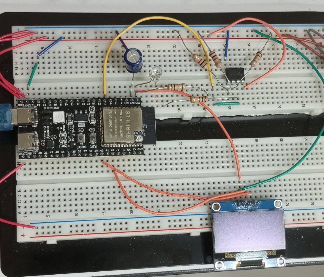
ขอเริ่มจากการใช้ตัวรับสัญญาณรีโมทความถี่ 38 KHz พร้อมกับการเขียน code สั้น ๆ …. อุปกรณ์ที่ใช้ตามภาพด้านล่างนี้เลยครับ

Code ทั้งหมดของการรับ protocol รีโมท

#include <Arduino.h>
#include <IRremoteESP8266.h>
#include <IRrecv.h>
#include <IRutils.h>

// Define the GPIO pin connected to the TSOP3848 OUT pin
const uint16_t kRecvPin = 4; 

// 1024 bytes is usually enough for long AC data packets
const uint16_t kCaptureBufferSize = 1024; 

// High timeout ensures the entire long AC frame is captured (in milliseconds)
const uint8_t kTimeout = 50; 

// Initialize the IR receiver object
IRrecv irrecv(kRecvPin, kCaptureBufferSize, kTimeout, true);
decode_results results;

void setup() {
  Serial.begin(115200);
  while (!Serial) {
    delay(50); // Wait for Serial Monitor to connect (needed for ESP32-S3 USB)
  }
  
  Serial.println("\n--- ESP32-S3 AC IR Decoder Starting ---");
  irrecv.enableIRIn(); // Start the receiver
  Serial.print("Listening for IR signals on GPIO ");
  Serial.println(kRecvPin);
}
void loop() {
  if (irrecv.decode(&results)) {
    Serial.println("==========================================");
    
    // Check if the protocol is recognized
    if (results.decode_type != decode_type_t::UNKNOWN) {
      Serial.print("Protocol Recognized! Brand: ");
      Serial.println(typeToString(results.decode_type));
    } else {
      Serial.println("Protocol: UNKNOWN (Not explicitly supported by the library yet)");
    }

    // Display basic information
    Serial.print("Value/Hex: 0x");
    serialPrintUint64(results.value, 16);
    Serial.println();
    Serial.print("Bits: ");
    Serial.println(results.bits);
    
    // Output the raw data in C++ format
    Serial.println();
    Serial.println("Raw Timing Data (Use this if protocol is UNKNOWN):");
    yield(); // Prevent watchdog triggers
    
    // FIX: Using the correct, built-in library function here
    String sourceCode = resultToSourceCode(&results);
    Serial.println(sourceCode);
    
    Serial.println("==========================================\n");
    
    // Resume listening for the next signal
    irrecv.resume(); 
  }
  delay(100);
}

ผมทดลองใช้รีโมทของแอร์ Carrier ยิงเข้าไปผลลัพธ์ที่ได้ก็ตามภาพด้านล่าง  protocol ที่อ่านได้จะมี 2 ส่วนที่สำคัญ ….
1. ส่วนแรกเรียกว่า raw data ก็คือจะเป็นชุดของตัวเลข 3 – 4 หลักหลายสิบชุด แต่ละตัวเลขคือค่าของ pulse width (หน่วย μs) ของสัญญาณ infrared ที่รีโมทตัวนั้นส่งออกมาเมื่อกดปุ่มนั้น ๆ
2. ส่วนที่ 2 คือ protocol ที่ใช้ง่ายมากก็คือเป็นตัวเลขที่เข้ารหัสแล้วเพียงบรรทัดเดียวเรียกว่า Hexadecimal (HEX) ซึ่งในการใช้งานเราก็เอาชุด HEX protocol บรรทัดเดียวนี่แหละครับไปใช้ใน code เพื่อส่งไปที่เครื่องใช้ไฟฟ้า/แอร์

สัญญาณ infrared ที่ส่งออกจากรีโมทจะเป็นลักษณะที่เรียกว่า Pulse train  คือเป็นคลื่นสี่เหลี่ยมที่มีสารพัด pulse width ต่อเนื่องกันยาวมาก ซึ่งจะส่งสั้นเพียง 0.15 – 0.25 วินาทีเท่านั้น


อย่างที่ 2 คือนำ protocol ที่รับได้จากการกดปุ่มรีโมทไปใช้  ก็คือเราก็จะต้องเอา HEX protocol ของรีโมทที่เรากดในปุ่มที่เราต้องการไปใส่ใน code  อย่างเช่นกดเปิดแอร์ , กดอุณหภูมิ 26 องศา , กดพัดลมเบา …. ทุกปุ่มที่เรากดมันก็จะให้ตัว protocol ที่แตกต่างกัน  การใช้งานในลักษณะเช่นนี้ก็คือสั่งเปิดเครื่องใช้ไฟฟ้าใด ๆ จากนอกบ้าน อย่างเช่นเรากำลังเดินทางกลับบ้านอากาศร้อนมากอยากจะเปิดแอร์ก็เพียงแค่หยิบมือถือขึ้นมาแล้วสั่งเปิดแอร์จาก web dashboard ในมือถือของเรา  และตัว ESP32 ที่บ้านก็จะส่งสัญญาณ protocol จาก infrared LED ไปที่แอร์เพื่อสั่งให้แอร์เปิด

ใน project ที่จะสาธิตนี้อุปกรณ์ที่ใช้เป็นไปตามภาพด้านล่างนี้ครับ

นี่คือคลิปที่สาธิตให้ดูว่า ESP32 สามารถส่งสัญญาณ infrared protocol จาก infrared LED เพื่อควบคุมแอร์แทนการกดรีโมทจริง ๆ ได้ …. ในคลิปหลังจากไฟสีแดงกระพริบ 9 ครั้งแล้วให้สังเกตที่ infrared LED 2 ตัวจะเห็นว่ามีจุดสว่างจาง ๆ ขึ้นแว้บนึง นั่นก็คือมันส่งคลื่นแสงอินฟราเรดไปที่แอร์และเราจะได้ยินเสียงแอร์ทำงานดัง “ตี๊ด”  ซึ่งปกติเราดวงตาจะมองไม่เห็นแสง infrared ที่ส่งจาก infrared LED นี้ แต่กล้องมือถือสามารถเห็นได้แบบจาง ๆ

Code ทั้งหมด

#include <Arduino.h>
#include <Wire.h>
#include <Adafruit_GFX.h>
#include <Adafruit_SH110X.h>
#include <IRremoteESP8266.h>
#include <IRsend.h>
#include <ir_Neoclima.h>

// OLED Display Configuration
#define SCREEN_WIDTH 128
#define SCREEN_HEIGHT 64
#define OLED_RESET     -1 // Share reset pin or set to -1 if not used
Adafruit_SH1106G display = Adafruit_SH1106G(SCREEN_WIDTH, SCREEN_HEIGHT, &Wire, OLED_RESET);

// Hardware Pins
const uint16_t kIrLedPin = 14; 
const uint16_t kIndicatorLedPin = 11; 
const int I2C_SDA_PIN = 40;
const int I2C_SCL_PIN = 42;

IRNeoclimaAc neoclimaAC(kIrLedPin);

// Intervals in milliseconds
const unsigned long INTERVAL_STATE_1_TO_2 = (3 * 60) * 1000UL; 
const unsigned long INTERVAL_STATE_2_TO_1 = (9 * 60) * 1000UL;       

bool isCurrentStateOne = true;
unsigned long previousMillis = 0;
unsigned long lastOledUpdateMillis = 0;

// Raw 12-byte states captured from the original remote control
uint8_t rawStateOne[12] = {0x00, 0x00, 0x00, 0x01, 0x00, 0x03, 0x00, 0x7A, 0x80, 0x2A, 0xA5, 0xCD};
uint8_t rawStateTwo[12] = {0x00, 0x00, 0x00, 0x01, 0x00, 0x02, 0x00, 0x7A, 0x80, 0x2D, 0xA5, 0xCF};

// Function declarations
void sendStateOne();
void sendStateTwo();
void flashLED(); 
void updateOLEDCountdown(unsigned long elapsed, unsigned long totalDuration, const char* stateName);

void setup() {
  pinMode(kIndicatorLedPin, OUTPUT); 
  
  // Initialize Custom I2C Pins for ESP32-S3
  Wire.begin(I2C_SDA_PIN, I2C_SCL_PIN);
  
  // Initialize SH1106 OLED (Address 0x3C is common for these modules)
  if(!display.begin(0x3C, true)) { 
    // If initialization fails, loop infinitely or handle error
    while(true);
  }
  
  display.clearDisplay();
  display.setTextColor(SH110X_WHITE);
  display.display();

  neoclimaAC.begin();
  
  // Initial transmission
  sendStateOne();
  previousMillis = millis(); 
  updateOLEDCountdown(0, INTERVAL_STATE_1_TO_2, "State One");
}

void loop() {
  unsigned long currentMillis = millis();
  unsigned long currentInterval = isCurrentStateOne ? INTERVAL_STATE_1_TO_2 : INTERVAL_STATE_2_TO_1;
  unsigned long elapsedMillis = currentMillis - previousMillis;

  // Update the countdown display once every second
  if (currentMillis - lastOledUpdateMillis >= 1000UL) {
    lastOledUpdateMillis = currentMillis;
    
    // Prevent elapsed from exceeding total interval before state switch clears it
    if (elapsedMillis > currentInterval) elapsedMillis = currentInterval; 
    
    updateOLEDCountdown(elapsedMillis, currentInterval, isCurrentStateOne ? "State One" : "State Two");
  }

  // State switching logic
  if (isCurrentStateOne) {
    if (elapsedMillis >= INTERVAL_STATE_1_TO_2) {
      sendStateTwo();
      isCurrentStateOne = false;     
      previousMillis = currentMillis; 
      lastOledUpdateMillis = currentMillis;
      updateOLEDCountdown(0, INTERVAL_STATE_2_TO_1, "State Two");
    }
  } else {
    if (elapsedMillis >= INTERVAL_STATE_2_TO_1) {
      sendStateOne();
      isCurrentStateOne = true;      
      previousMillis = currentMillis; 
      lastOledUpdateMillis = currentMillis;
      updateOLEDCountdown(0, INTERVAL_STATE_1_TO_2, "State One");
    }
  }
}

void updateOLEDCountdown(unsigned long elapsed, unsigned long totalDuration, const char* stateName) {
  long remainingSeconds = (totalDuration - elapsed) / 1000UL;
  if (remainingSeconds < 0) remainingSeconds = 0;

  int minutes = remainingSeconds / 60;
  int seconds = remainingSeconds % 60;

  display.clearDisplay();
  
  // Header: Active State
  display.setTextSize(1);
  display.setCursor(0, 4);
  display.print("Sending: ");
  display.println(stateName);
  
  // Visual divider line
  display.drawFastHLine(0, 18, 128, SH110X_WHITE);

  // Large Countdown Display
  display.setTextSize(2);
  display.setCursor(12, 32);
  
  // Format matching: "3m 30s" or "9m 0s"
  display.print(minutes);
  display.print("m ");
  display.print(seconds);
  display.print("s");
  
  display.display();
}

void flashLED() {
  for (int i = 0; i < 9; i++) {
    digitalWrite(kIndicatorLedPin, HIGH);
    delay(166); 
    digitalWrite(kIndicatorLedPin, LOW);
    delay(167); 
  }
}

void sendStateOne() {
  flashLED(); 
  neoclimaAC.setRaw(rawStateOne);
  neoclimaAC.send();
}

void sendStateTwo() {
  flashLED(); 
  neoclimaAC.setRaw(rawStateTwo);
  neoclimaAC.send();
}